How are Air Fin Coolers designed and how do they work?
Air Fin Coolers are essential components in process industries where air-based heat rejection is required. Their design directly impacts thermal efficiency, plant reliability, and maintenance intervals. Understanding the key engineering principles behind these systems enables operators and engineers to optimize long-term performance. Learn more about available configurations and performance data on our Air Fin Cooler product page.
How do Air Fin Coolers operate?
Air Fin Coolers function as dry-type heat exchangers that use ambient air as the cooling medium. They are commonly employed in process industries such as oil & gas, petrochemicals, power generation and hydrogen production, where water scarcity or environmental restrictions make wet cooling systems impractical.
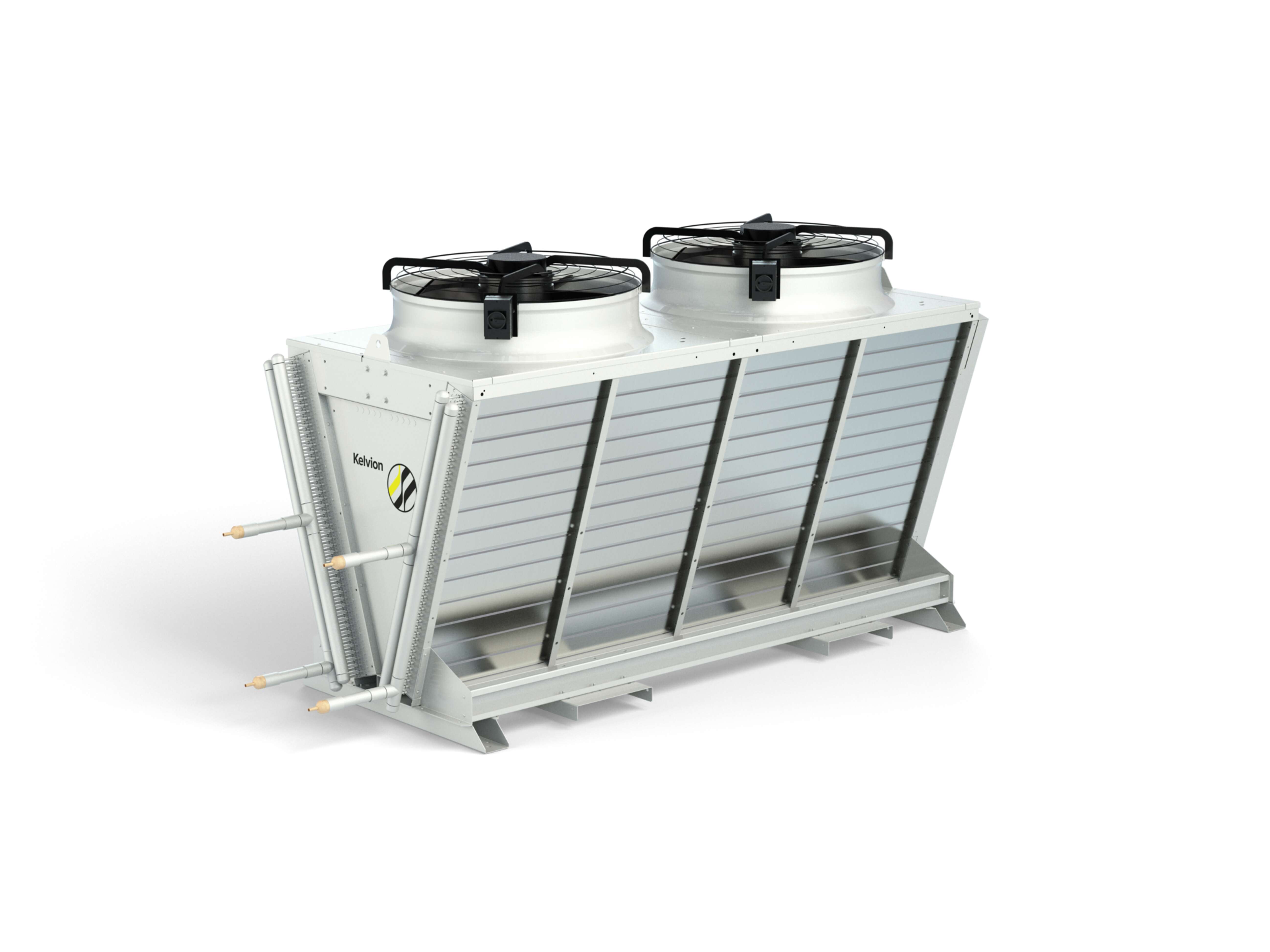
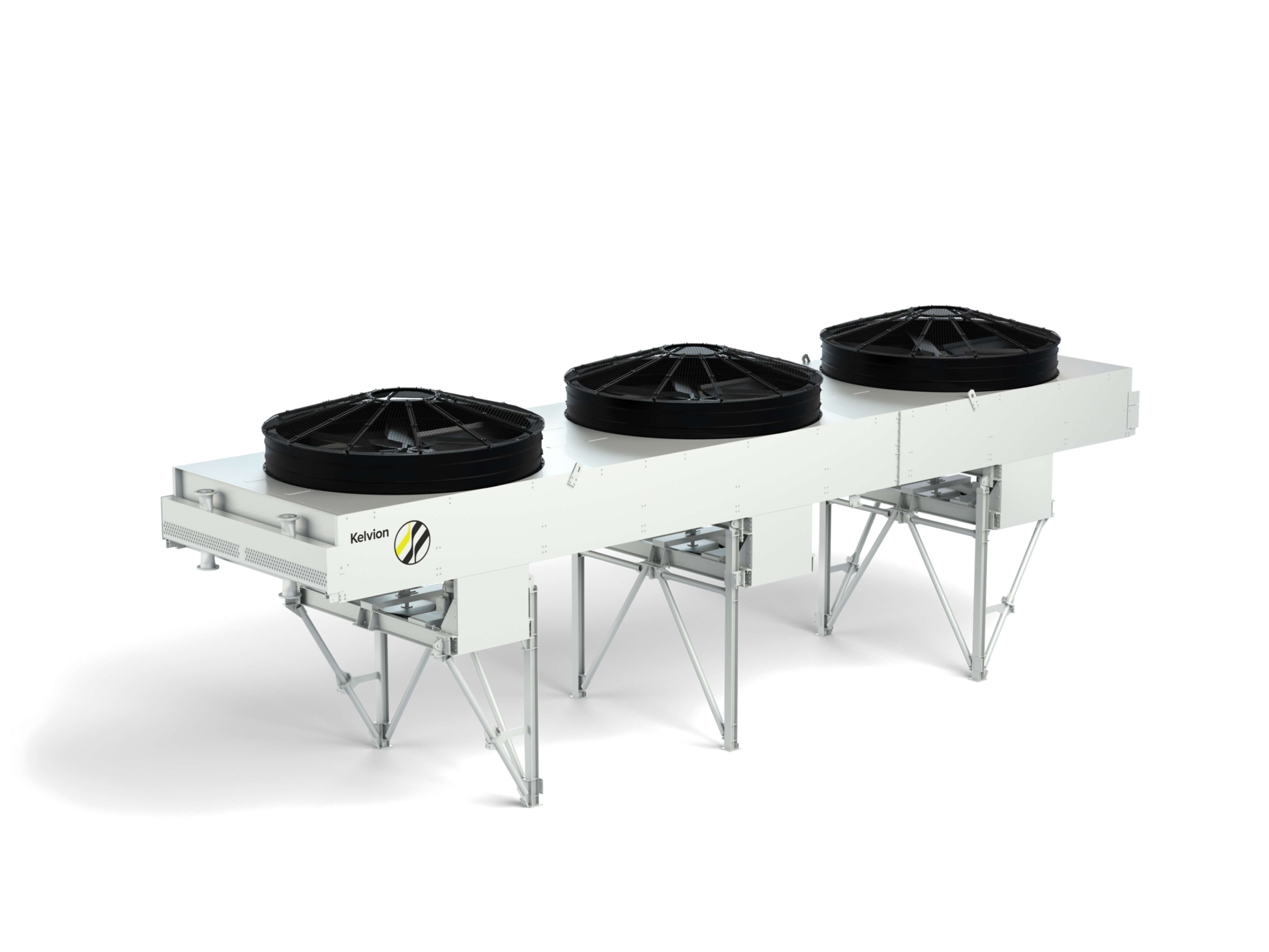
Process fluids — typically hydrocarbons, condensates, or compressed gases — enter the Air Fin Cooler through inlet headers and flow through a network of finned tubes. Axial fans mounted below or above the tube bundle drive a continuous air stream across the extended fin surfaces. As the air passes over the fins, heat is transferred from the fluid inside the tubes to the surrounding atmosphere by convection.
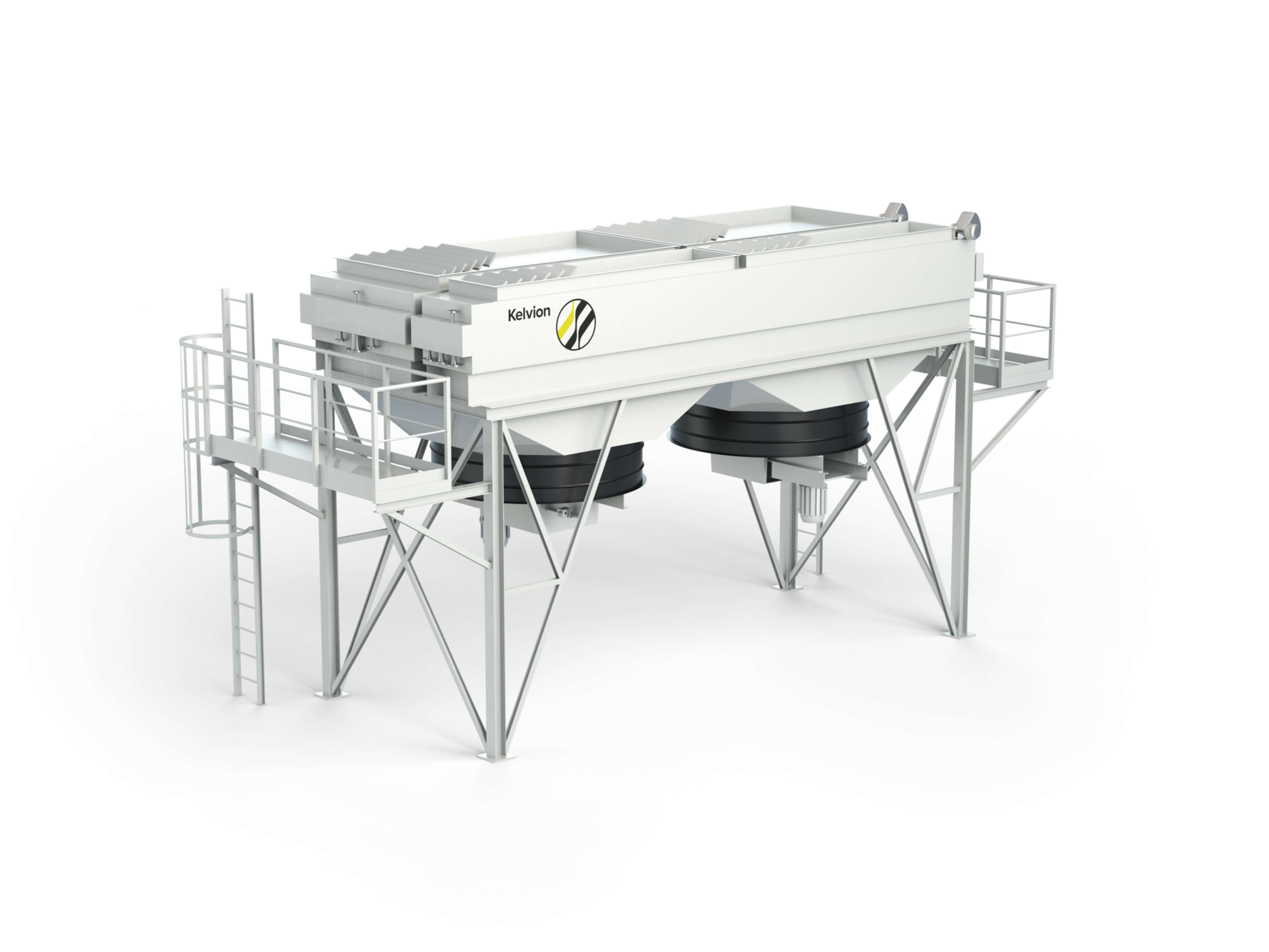
Forced-draft vs. induced-draft configurations
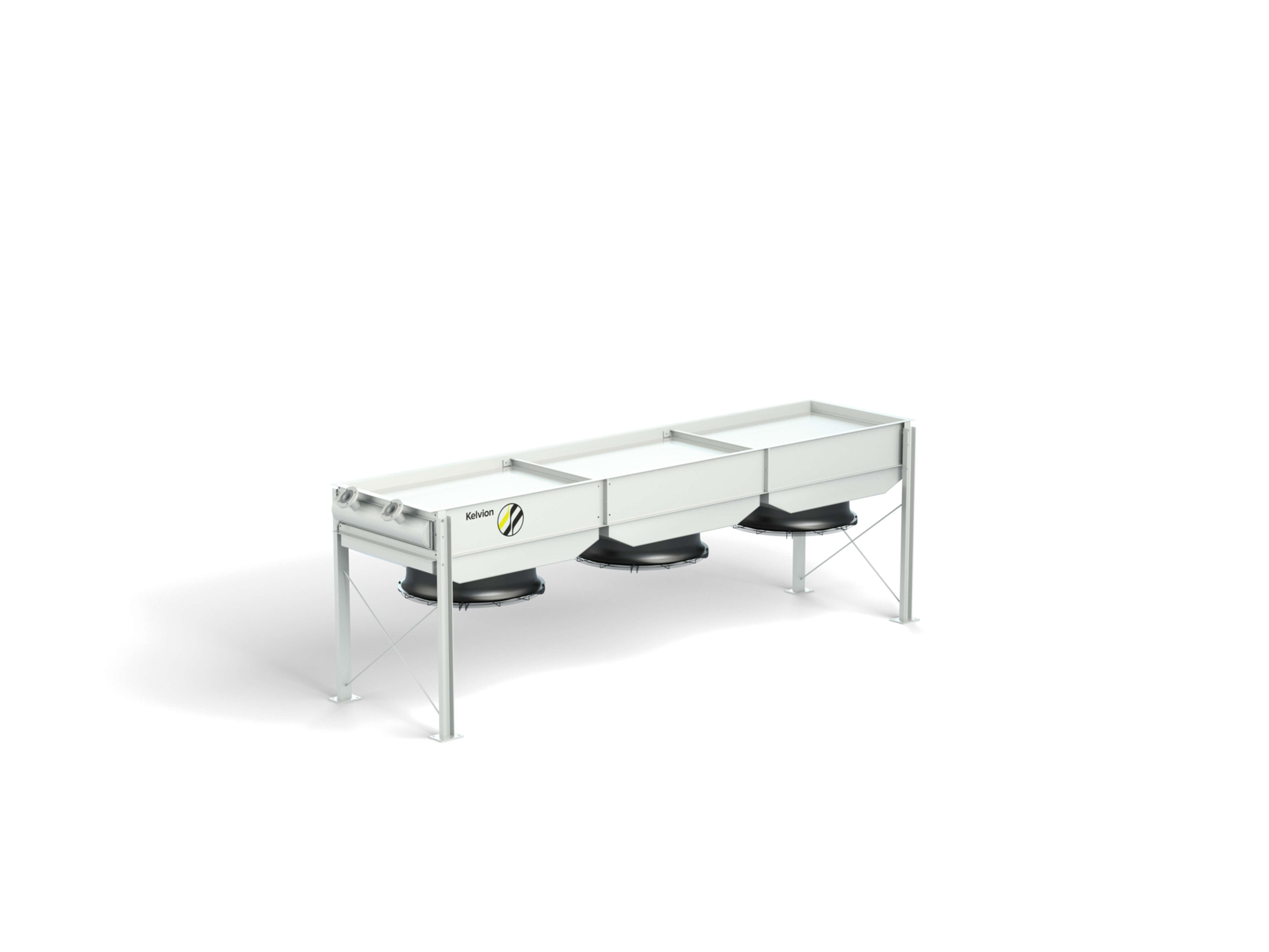
Depending on process requirements and site layout, two main configurations are used. In forced-draft designs, fans are positioned beneath the tube bundle, pushing air upward through the fins. This arrangement allows easier fan maintenance and prevents recirculation of hot air but exposes motors to higher temperatures. In induced-draft systems, fans are installed above the bundle, pulling air through the tubes to achieve more uniform airflow and lower exit air velocity — an advantage in hot or dusty environments.
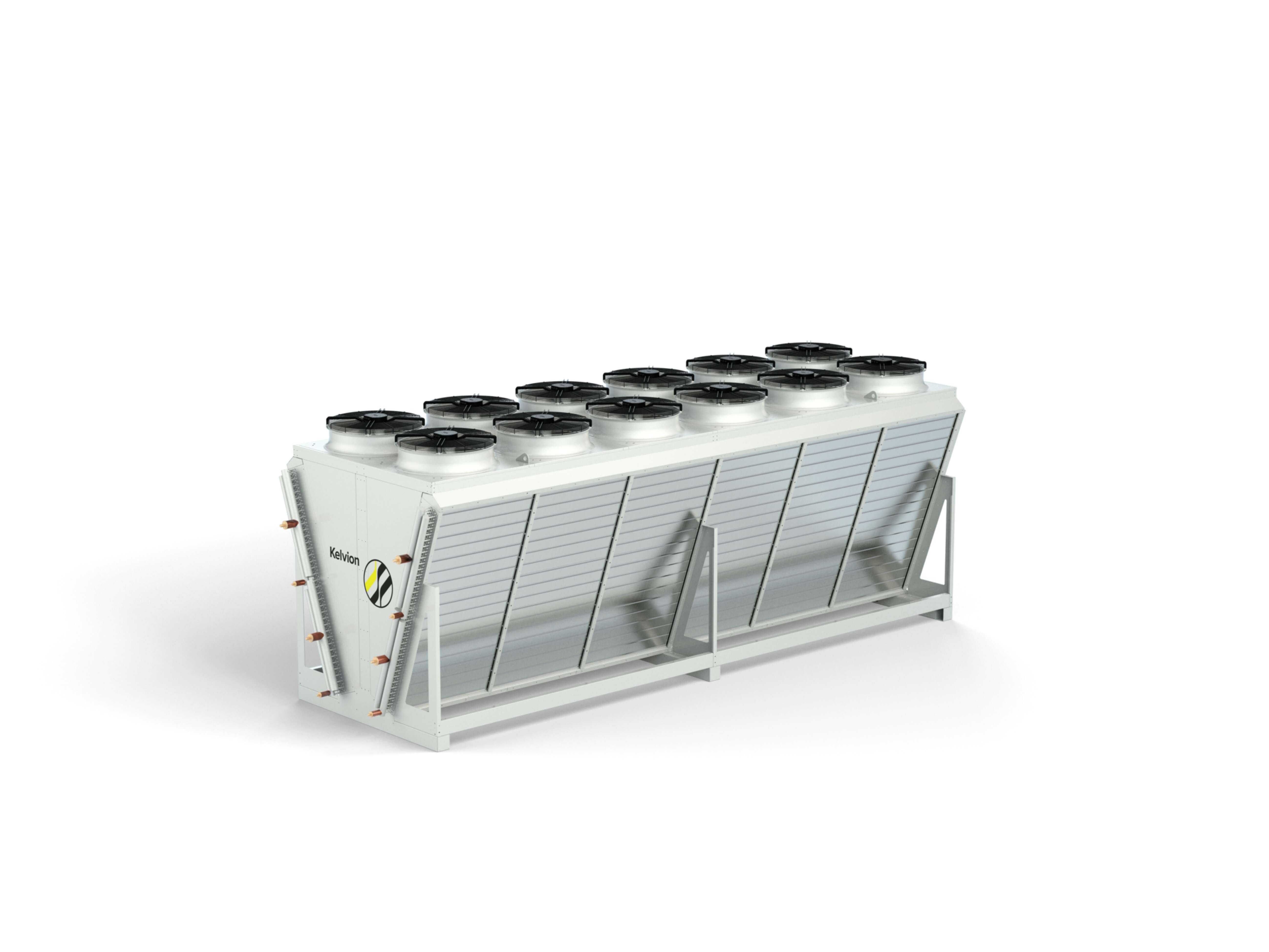
Air Fin Coolers can be arranged in multiple bays, each containing several tube bundles, fans, and plenum sections. The modular design enables scalability for different process loads and simplifies transportation and installation. Flow control systems — such as louvers or automatic dampers — regulate the air volume and maintain target outlet temperatures even under fluctuating ambient conditions.
The thermal performance of the unit depends on ambient air temperature, air velocity, fin geometry, and tube configuration. The balance between these parameters determines the achievable approach temperature and energy efficiency. To ensure stable operation, engineers integrate vibration control, motor monitoring and automatic start/stop sequences into the system’s control logic.
By relying solely on air as the cooling medium, Air Fin Coolers offer a robust and environmentally sustainable solution for continuous operation in demanding industrial settings. Their dry-cooling design eliminates water consumption, reduces maintenance effort, and ensures reliable performance across a wide range of climatic zones — from coastal installations to desert environments.
Engineering Design Principles
Designing an Air Fin Cooler involves a combination of thermal, mechanical and structural engineering disciplines. Each design begins with a detailed process analysis, defining the required duty, fluid properties and site conditions. From there, engineers calculate the optimal heat-transfer area, tube geometry and fin characteristics to achieve the specified outlet temperatures at minimal power input.
Key parameters such as air mass flow, fin efficiency and overall heat-transfer coefficient (U-value) are determined using specialised calculation tools. These values guide the selection of tube types, materials and fan configurations. Proper sizing ensures a balance between thermal performance, mechanical integrity and energy efficiency — the three critical pillars of cooler design.
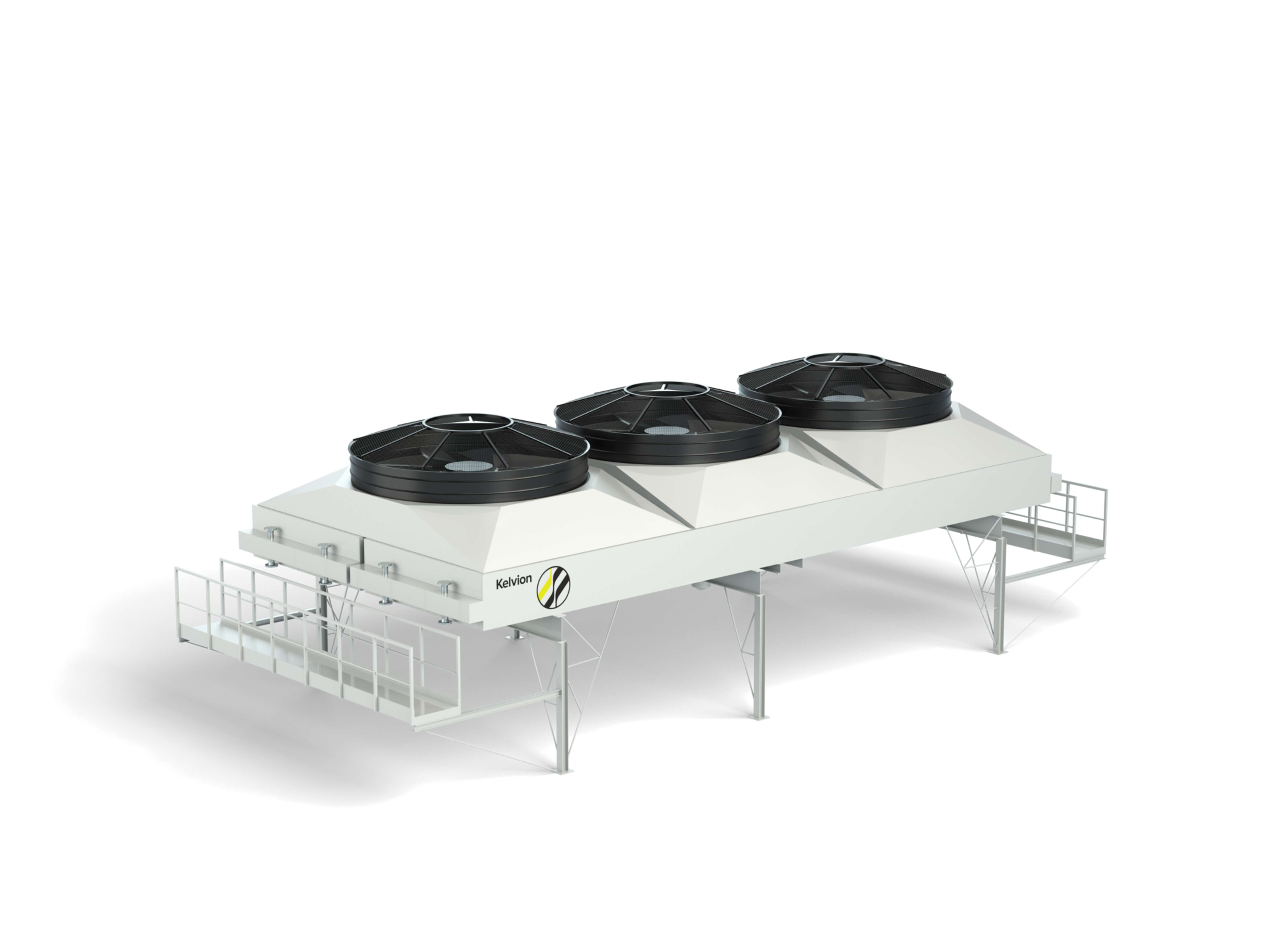
Balancing thermal performance and operational efficiency
A central challenge lies in optimising pressure drop: higher air velocities increase heat transfer but also raise fan power demand. Engineers use Computational Fluid Dynamics (CFD) simulations to visualise air distribution and identify flow maldistribution within the bay. This allows for targeted design improvements such as modified fin spacing or redesigned fan blades.
In industrial applications like refineries, power plants or gas compression stations, units must also comply with API 661 and ASME standards, ensuring mechanical robustness and safety under varying process pressures and thermal loads. Vibrations, thermal expansion and dynamic stresses are analysed through finite element modelling (FEM) to guarantee long-term stability and minimise the risk of tube fatigue.
Modern designs further incorporate variable-frequency drives (VFDs) to adapt fan speed to real-time cooling demand, reducing energy consumption and extending component lifespan. Combined with smart monitoring systems and predictive analytics, these technologies enable continuous performance tracking and early fault detection — key elements of a sustainable plant operation.
Comprehensive engineering drawings define all major components — including tube arrangement, fan bay layout, and header design. These documents are essential for fabrication, QA/QC and site assembly.
3D CAD models and digital twins are increasingly adopted to assess airflow behaviour, ensure mechanical clearance, and support predictive maintenance strategies throughout the asset lifecycle.
Material choice significantly affects operational lifetime. Aluminium fins combined with carbon-steel or stainless-steel tubes provide a proven balance between thermal performance and corrosion resistance.
For coastal or chemically aggressive environments, additional protective coatings such as epoxy or polyurethane are applied. Fin pitch and wall thickness are adapted to mitigate thermal stress and resist vibration fatigue, ensuring reliability under continuous operation.
FAQ: Air Fin Cooler Functionality and Design
Thermal performance is influenced by several interconnected parameters: airflow velocity, fin geometry, tube configuration and process-fluid properties. Higher air velocity increases heat transfer but also raises pressure drop and fan power consumption. Fin geometry (spacing, thickness, material) determines how effectively heat is conducted away from the tubes. Additionally, the type and viscosity of the process fluid affect internal convection rates. Engineers optimise these factors through detailed thermal calculations and CFD simulations to achieve maximum efficiency at minimal operating cost.
Fins significantly increase the surface area available for heat exchange between the process fluid and ambient air. By extending the surface, they enable more effective dissipation of thermal energy from the tube wall. In modern Air Fin Coolers, extruded or embedded fins ensure strong mechanical bonding and enhanced durability. The fin design — including material, height, and spacing — must be tailored to the specific operating conditions to balance efficiency, cost, and fouling resistance.
Noise control in Air Fin Coolers is achieved through a combination of aerodynamic fan design, motor speed control, and sound-dampening enclosures. Low-noise fan blades with optimised pitch angles reduce turbulence, while variable-speed drives allow operators to adapt fan rotation to cooling demand, lowering noise during part-load operation. In sensitive environments such as refineries or urban installations, additional acoustic barriers and silencers are integrated to ensure compliance with regulatory noise limits.
With proper material selection, corrosion protection and regular maintenance, modern Air Fin Coolers can achieve service lifetimes of 20 to 25 years or longer. Factors such as ambient conditions, operating cycles and cleaning frequency influence this lifespan. Routine inspections of fin integrity, fan bearings and tube connections help detect early signs of wear. When combined with predictive maintenance tools and modular component replacement, downtime can be reduced to a minimum.
Computational Fluid Dynamics (CFD) plays a crucial role in the design and optimisation process. By simulating airflow, heat transfer and temperature gradients within the unit, CFD enables engineers to visualise potential inefficiencies such as dead zones or uneven heat distribution. This allows for precise adjustments to fin geometry, fan positioning or bay layout before manufacturing begins. The result is a more energy-efficient and reliable system tailored to the specific requirements of the industrial site.