How to Improve Data Centre Cooling Efficiency – FAQ
Efficient data-centre cooling comes from holding a stable approach temperature (ΔT), maximising free-cooling hours, and matching the white-space architecture (air or liquid) to actual heat flux and rack density – without compromising water stewardship or uptime. The answers below start broad (strategy and trade-offs) and progress toward practical, technical measures you can apply in design, retrofit, and operations.
How to make data centres more efficient without raising risk?
Start with the fundamentals in the white space, then make sure the outside plant can hold those gains on the hottest days.
White-space first (airflow, set-points, hygiene)
Eliminate bypass and recirculation with consistent hot-/cold-aisle containment, blank unused rack space, and seal floor cut-outs. Right-size airflow so you are not paying for unnecessary airflow volume (CFM/L·s), and coordinate unit set-points to prevent hunting between CRAC/CRAH, in-row or rear-door units. Lift supply temperatures within hardware limits and keep coils clean so the approach (ΔT) does not widen under load.
Outdoor train sized for design day
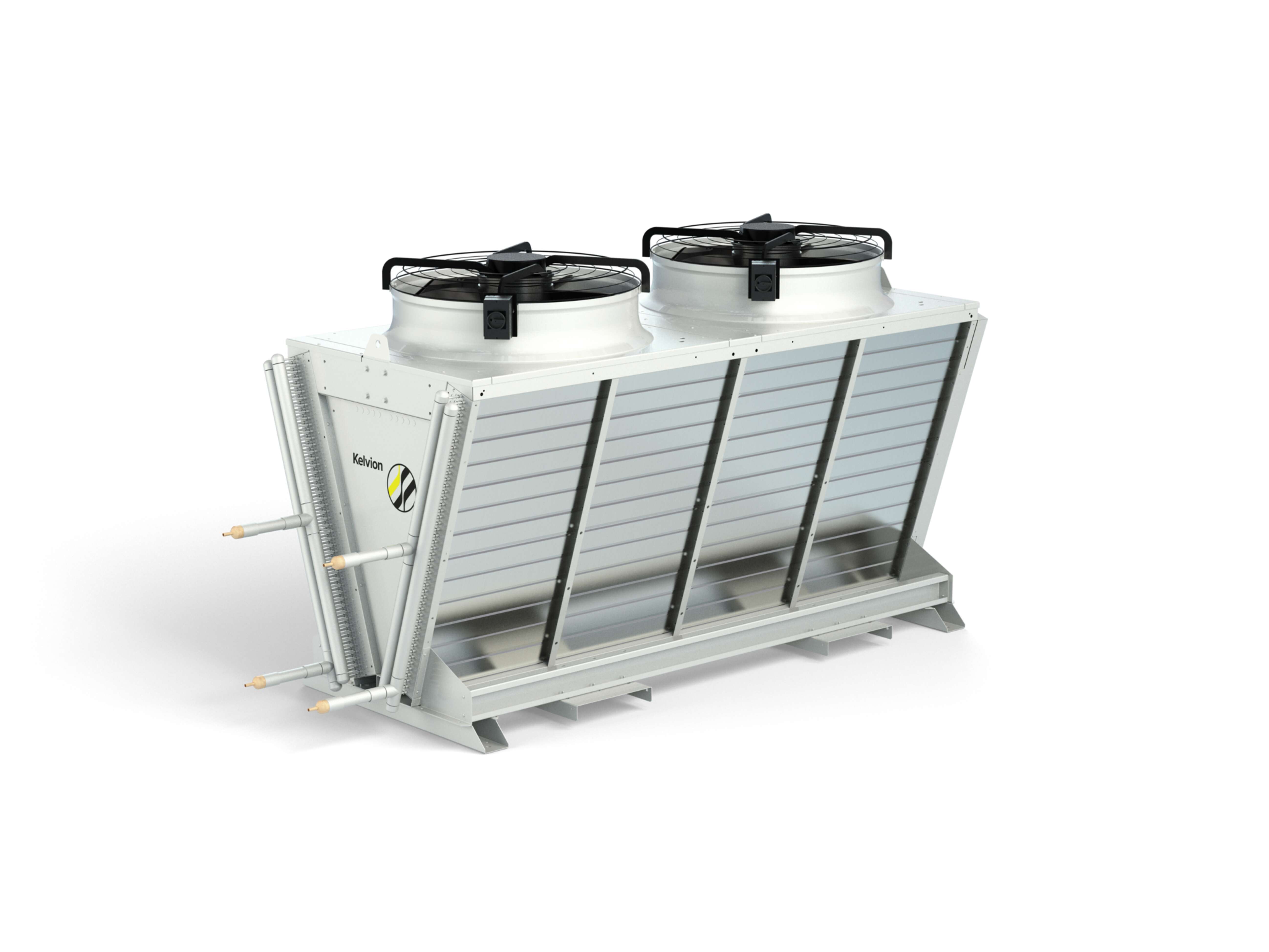
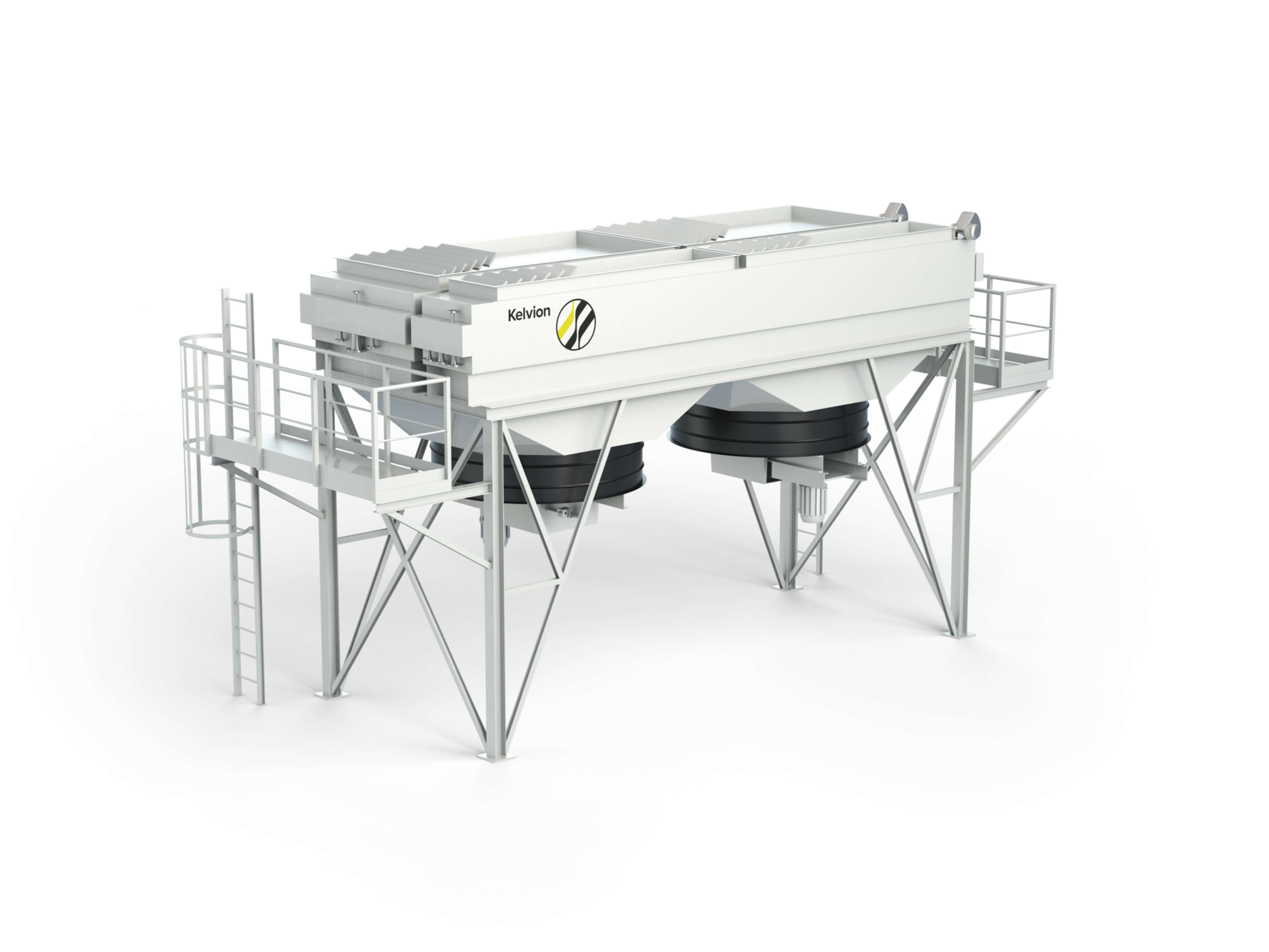
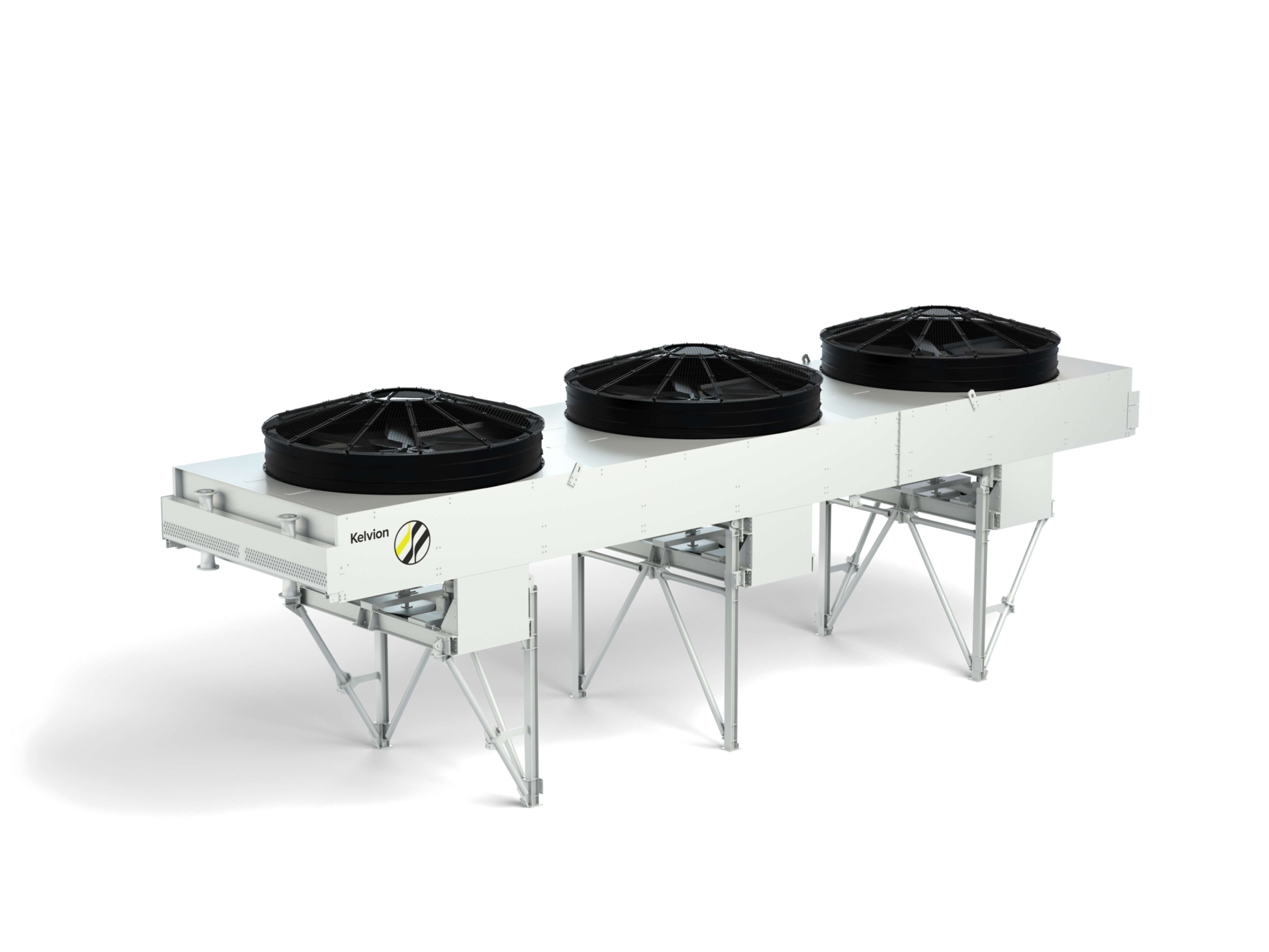
Use a dry/air-fin baseline and keep adiabatic or hybrid only as a peak assist. The plant must be able to hold set-points at worst-case ambient; otherwise, any indoor optimisation will be eroded on hot days.
Control & maintenance practices that lock in savings:
- Apply variable-speed drives on fans and pumps where it helps, so the system follows IT load and climate smoothly.
- Treat coil and plate cleanliness as a power-bill item; fouling shows up first as a widening ΔT and rising parasitics.

How do I reduce water use and remain efficient (WUE)?
A low-water strategy starts with dry/air-fin as the baseline so the plant can operate dry for most of the year. Capacity at the extreme few hours is then protected by adiabatic or hybrid modes engaged briefly to lower intake-air temperature and keep approach and set-points in tolerance. In climates with long dry windows this approach limits WUE, preserves free-cooling hours and stabilises ΔT. If you introduce liquid zones for high-density areas, target warmer coolant set-points and retain dry rejection to avoid shifting water use upward unnecessarily. Controls are critical: stage fans sensibly, apply economiser logic that prioritises dry operation, and interlock water assist so it only engages under defined ambient thresholds.
- Validate peak-ambient capacity dry first; treat water assist as insurance, not as baseline.
- Track WUE alongside ΔT so peak-day protection does not become everyday drift.
Where do free cooling and heat recovery fit?
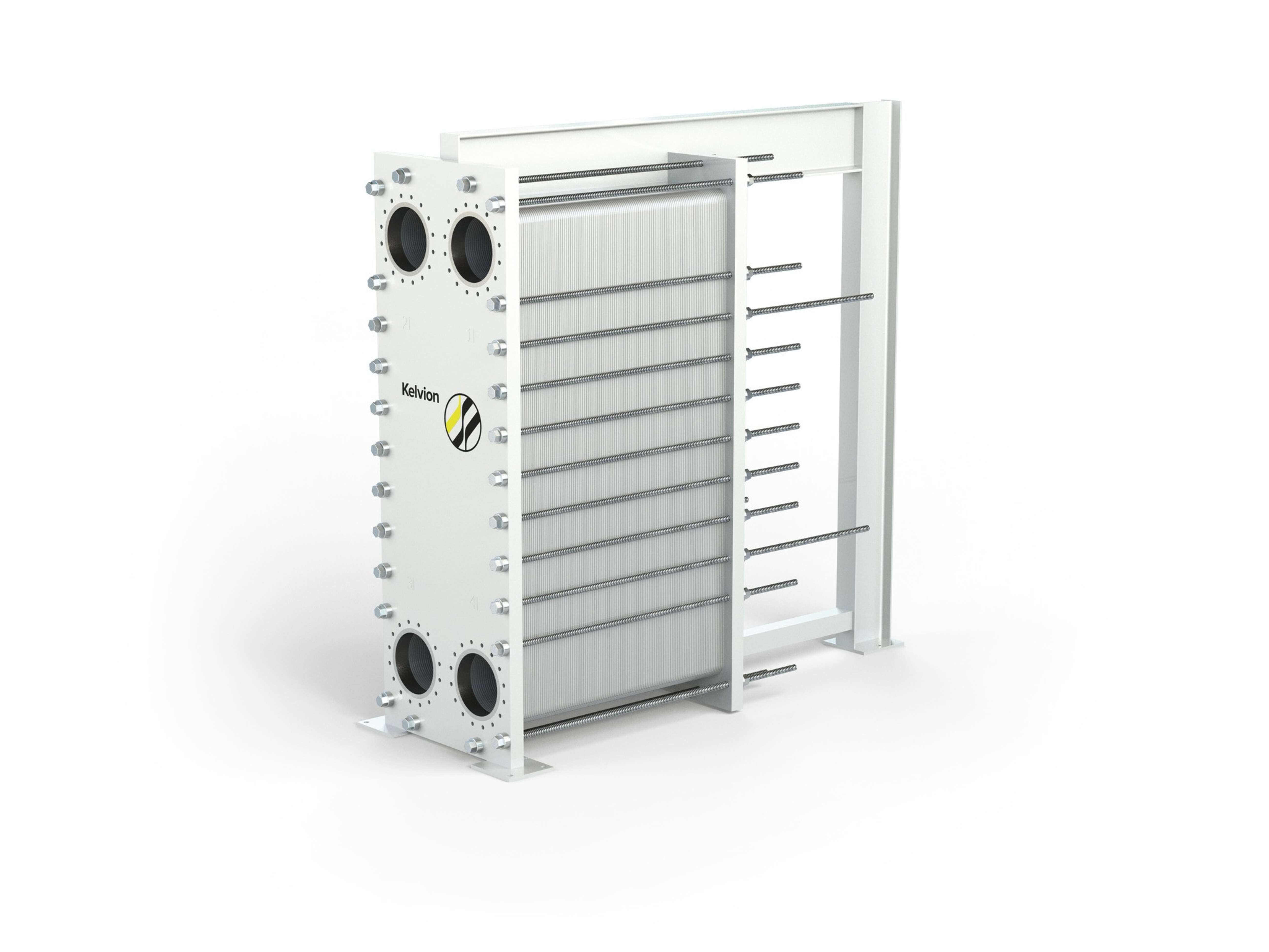
Free cooling reduces both electrical and water consumption by keeping outdoor equipment in dry mode whenever climate allows; the more hours you can run dry at your required set-points, the better your efficiency story. Waste-heat recovery (WHR) adds a second lever by exporting stable return heat to a building or district network. In practice, WHR uses hydraulic separation (plate or shell-and-tube exchangers) and, when required by the network, a heat-pump stage to lift temperature to supply set-points. Buffer tanks help decouple data-centre load from network demand and metering (supply/return, ΔT, flows, availability) verifies that export does not undermine core cooling.
- Free-cooling windows and WHR are complementary: maximise dry hours first, then monetise surplus heat when temperatures and offtake are dependable.
- Keep the recovery path optional so base cooling remains unaffected during peak ambient or network outages.

When should I consider liquid alongside air?
Short answer: switch (or add) liquid cooling when heat density, control needs, or space limits make air inefficient—then deploy it selectively in the zones that benefit most.
For a short comparison of approaches, see the Liquid vs. Air Cooling in Data Centres – FAQ.
- High heat flux / density (AI, HPC): air paths get large, noisy, and power-hungry.
- Tight thermal envelopes: you must hold narrow, stable temperatures to protect performance and lifetime.
- Space constraints: limited floor area leaves no room for bigger air corridors or more CRAH/CRAC capacity.
- Keep air for mainstream racks.
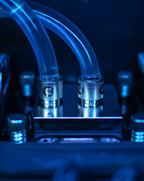
- Add liquid in hot zones and choose the fit:
- Direct-to-chip (DTC): preserves rack-centric workflows and simpler logistics.
- Immersion: maximises rack power density and lowers acoustics.
- Warmer return temperatures from liquid loops expand free-cooling windows.
- Better heat-recovery viability when coupled to a heat-pump interface (if the network requires a temperature lift).
- Use dry/air-fin coolers as a low-water baseline; keep adiabatic/hybrid only for design-day resilience so set-points hold at peak ambient.

FAQ – Efficient Data Centre Cooling Detailed
Before moving to liquid, many sites can harvest quick wins on the air side. Focus on measures that eliminate bypass, allow higher supply temperatures, and protect ΔT at peak ambient: consistent hot-/cold-aisle containment, blanking panels and brush grommets, sealed cut-outs, and right-sized airflow across CRAC/CRAH, in-row or rear-door units. Add variable-speed control to track load and weather smoothly, and keep coils clean with filter classes suited to your environment (e.g., ISO ePM1) so pressure drop and ΔT stay in check.
- If pockets run hot, stabilise with in-row or rear-door units before a broader liquid rollout.
- Document set-point philosophy so operators do not “chase” alarms by lowering temperatures unnecessarily.
A tight but controllable ΔT between white space and outdoor train usually lowers power, provided surfaces are clean and controls remain stable at design-day ambient. The wrong target is one you can only hold in spring; the right target is one that stays inside limits when the site is hottest and most loaded. Trend ΔT across coils and plates as an early fouling indicator and budget time for cleaning before parasitics climb or free-cooling hours disappear.
- Design coils/plates and select fan curves so the plant doesn’t need water assist to meet normal set-points.
- Expect ΔT to drift seasonally; manage by maintenance, not by permanently lowering supply temperatures.
Plan for the worst hour of the year using local dry-bulb and wet-bulb data, then size dry/air-fin capacity accordingly. Apply adiabatic or hybrid as a short-duration margin to protect approach temperature and compressor-less operation when intake air is briefly too warm. In coastal or industrial settings, specify protective coil coatings and robust filtration to limit corrosion, fouling, and ΔT drift. Where heat flux and acoustic limits are severe, a liquid zone with warmer set-points plus dry rejection can stabilise thermals and reduce fan power without committing the whole hall to liquid.
- Controls should be monotonic and predictable: avoid oscillation by coordinating valves, VFDs, and set-points.
- Maintain coils proactively; humidity plus contaminants accelerates approach degradation.
Start where ROI is highest and disruption lowest. Phase air-side optimisations first (containment, airflow balance, coil hygiene, tighter controls), then introduce direct-to-chip or immersion in the hottest zones. On the outdoor side, deploy modular dry fields and keep adiabatic/hybrid only for peaks. Use plate heat exchangers for hydraulic separation, design clear bypass and isolation for maintenance, and provision N+1 where required so work can proceed safely in live environments.
- Reserve space, power and headers for future liquid loops to keep expansion predictable.
- Align maintenance windows with seasonal loads to preserve free-cooling hours.
Both topologies increase resilience, but they behave differently at part load. N+1 often optimises CapEx/OpEx while maintaining availability; N+N raises fault tolerance but can increase parasitics if standby capacity runs too often or too hard. The remedy is control philosophy: use variable-speed drives, lead/lag rotation, and sensible turndown so standby equipment does not quietly erode PUE.
- Test switchover and failover under realistic ambient to validate that ΔT and set-points hold.
- Monitor standby power as a KPI; it should be low and stable, not a hidden base load.
A concise metric set keeps systems honest and flags deterioration early. Track ΔT/approach across coils and plates to catch fouling and control drift; measure fan and pump power vs IT load to verify parasitic reductions; log supply and return temperatures for thermal headroom; and trend PUE and WUE so efficiency and water stewardship improve together. Add targeted alarms for leaks, flows and temperature excursions to protect reliability.
- Investigate widening ΔT before it forces lower supplies or increased water use.
- Review trends monthly; seasonal patterns reveal where cleaning or control tuning delivers the biggest payback.
Mining workloads concentrate very high, steady heat flux in compact footprints (often containerised), with tight acoustic limits and rapid scale-outs. Compared with typical data-centre IT, that means:
- Higher rack/pod densities and more uniform, 24/7 thermal load profiles.
- Edge/container deployments with limited floorspace and service access.
- Stronger emphasis on modular growth and predictable ΔT at peak ambient.
For efficiency options and architectures, see How to Improve Crypto Mining Efficiency – FAQ.