Waste Heat Recovery in Data Centres – FAQ
Data centres release large volumes of low- to medium-grade heat. Waste Heat Recovery (WHR) captures this energy from IT and cooling loops and delivers it for space heating, district networks or process pre-heat. Done well, WHR lowers emissions, improves overall energy utilisation and can, where a network exists, create cost offsets or revenue.
What is waste heat recovery – and why consider it?
WHR is the capture, transfer and, where needed, temperature lift (via heat pump) of data-centre waste heat for use elsewhere (e.g., buildings, district/communal heating).
Heat quality. The value of recoverable heat depends on temperature level and stability. Liquid-cooled IT (direct-to-chip/immersion) typically offers higher return temperatures than air-cooled white space, improving downstream heat-pump COP and the usability of exported heat.
Business & operations
- Decarbonisation lever: displaces fossil heat on connected networks.
- Yield & risk: potential income/savings, dependent on network demand, tariffs and availability commitments.
- Operational fit: integration must preserve approach temperature (ΔT) and core cooling KPIs (PUE/WUE, uptime).

Where can waste heat be captured?
- IT liquid loops (direct-to-chip or immersion): comparatively higher, more stable return temperatures; strong WHR candidates.
- Secondary glycol/water loops serving dry/air-fin, hybrid or adiabatic coolers: export via plate or shell-and-tube heat exchangers with hydraulic separation.
- Chilled-water or condenser-water loops in mechanical schemes: couple through a heat-pump interface sized to network set-points.
- Direct coupling when temperatures meet downstream needs (uncommon; mainly in shoulder seasons).
- With heat pump (typical): lifts to district/communal supply temperatures (e.g., ~60–90 °C, network-dependent).
- Buffers & timing: thermal buffer tanks smooth mismatch between IT load and network demand and reduce cycling of heat-pump stages.
Which technologies are used for rejection and recovery?
Waste heat projects combine heat rejection (to safeguard cooling in all conditions) with heat recovery (to export useful heat when there is demand). In practice, sites use a portfolio that can be mixed and phased:
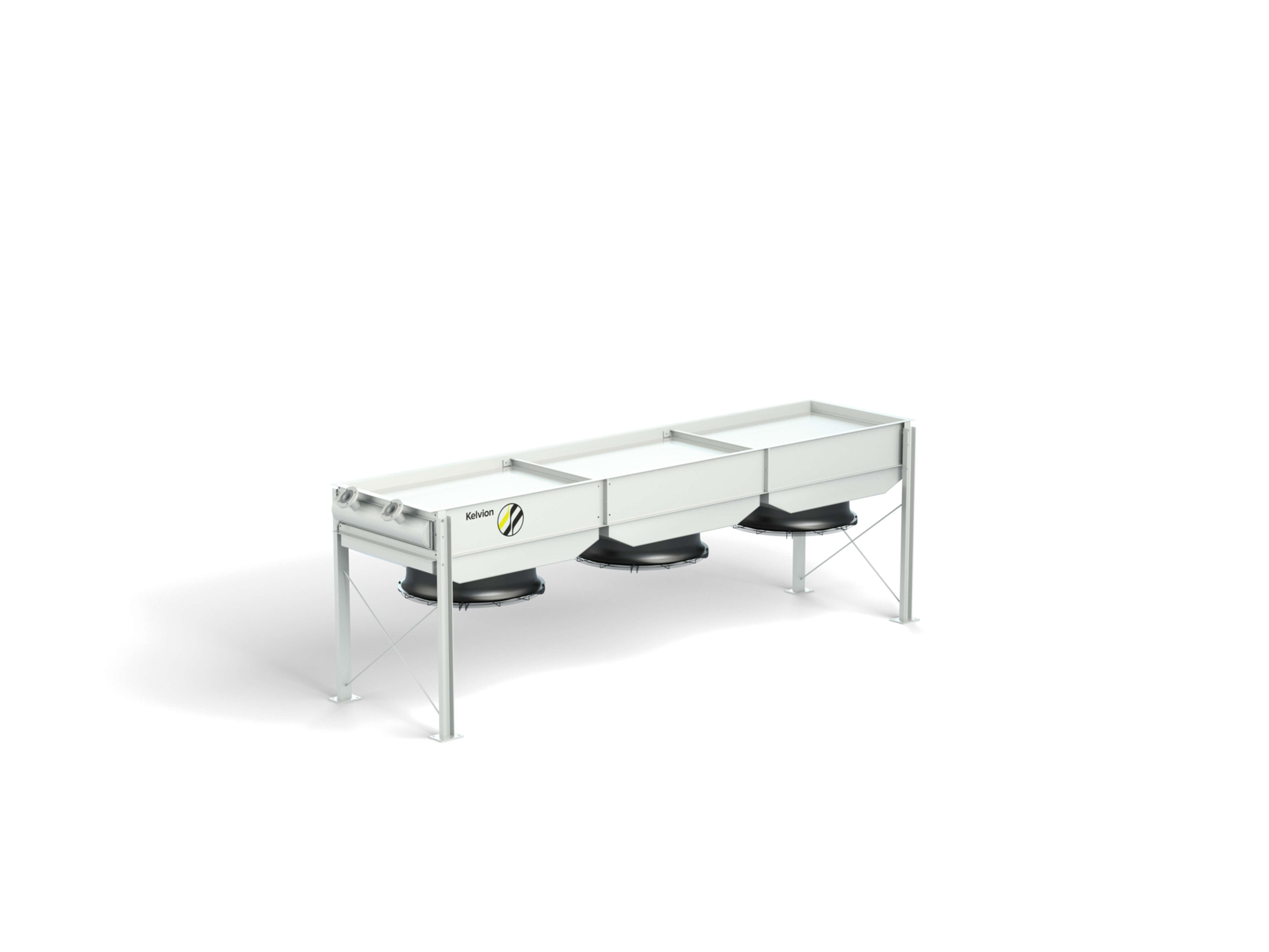
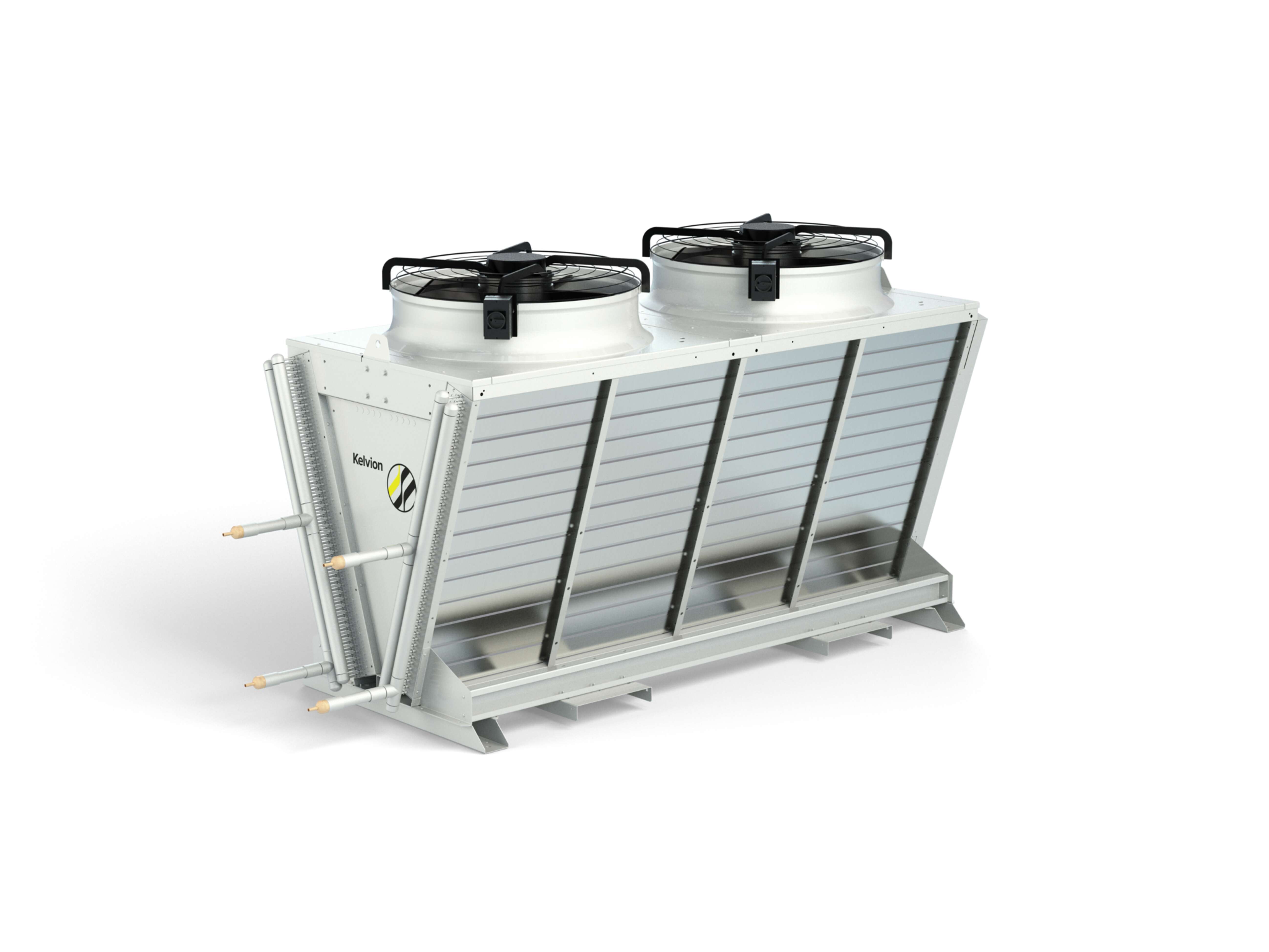
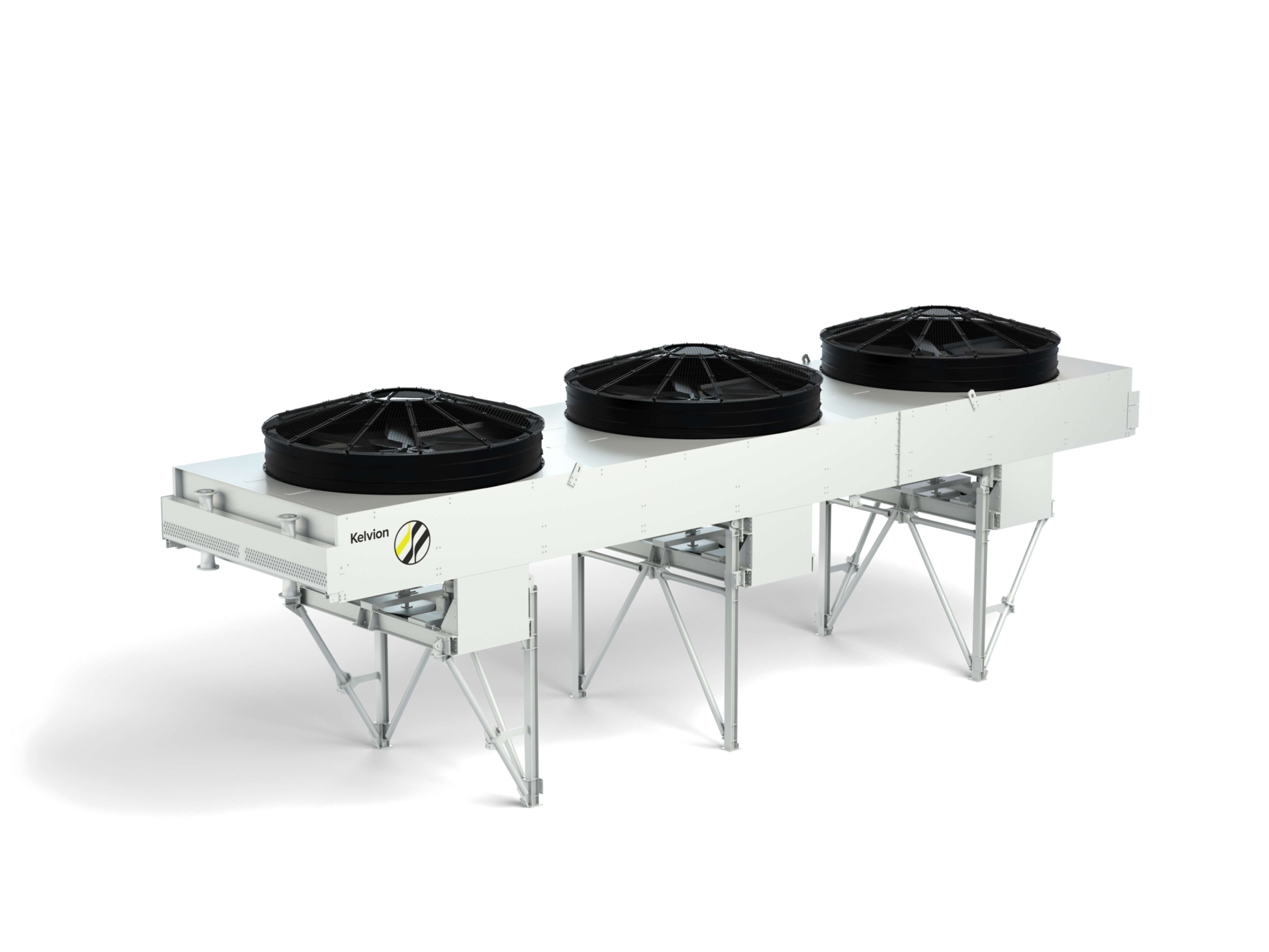
Dry, water-saving heat rejection with predictable OPEX; rooftop or site-erected fields; stable approaches when sized to peak ambient.
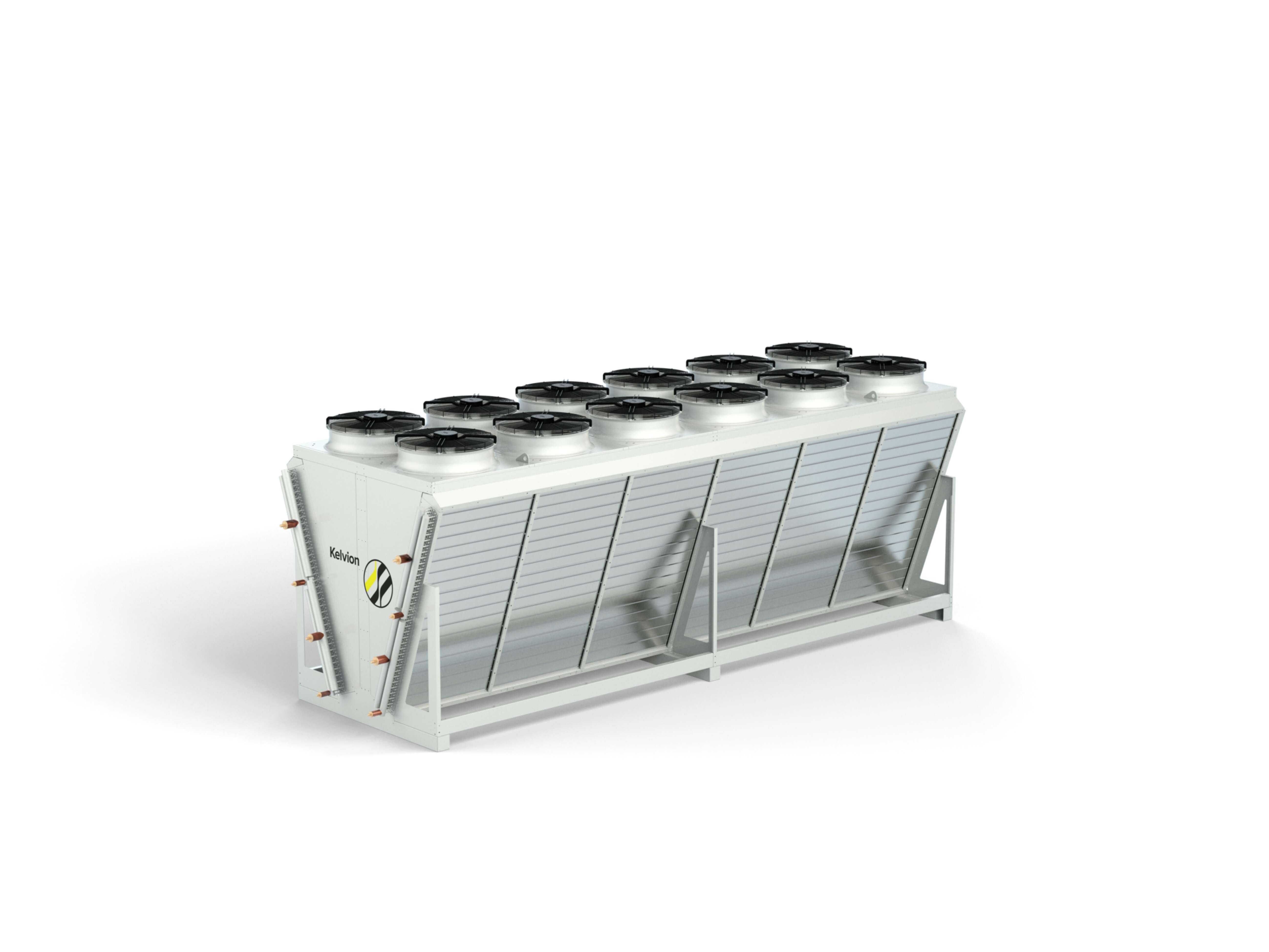
Dry most of the year; adiabatic assist on hot days to lower intake-air temperature and add capacity.
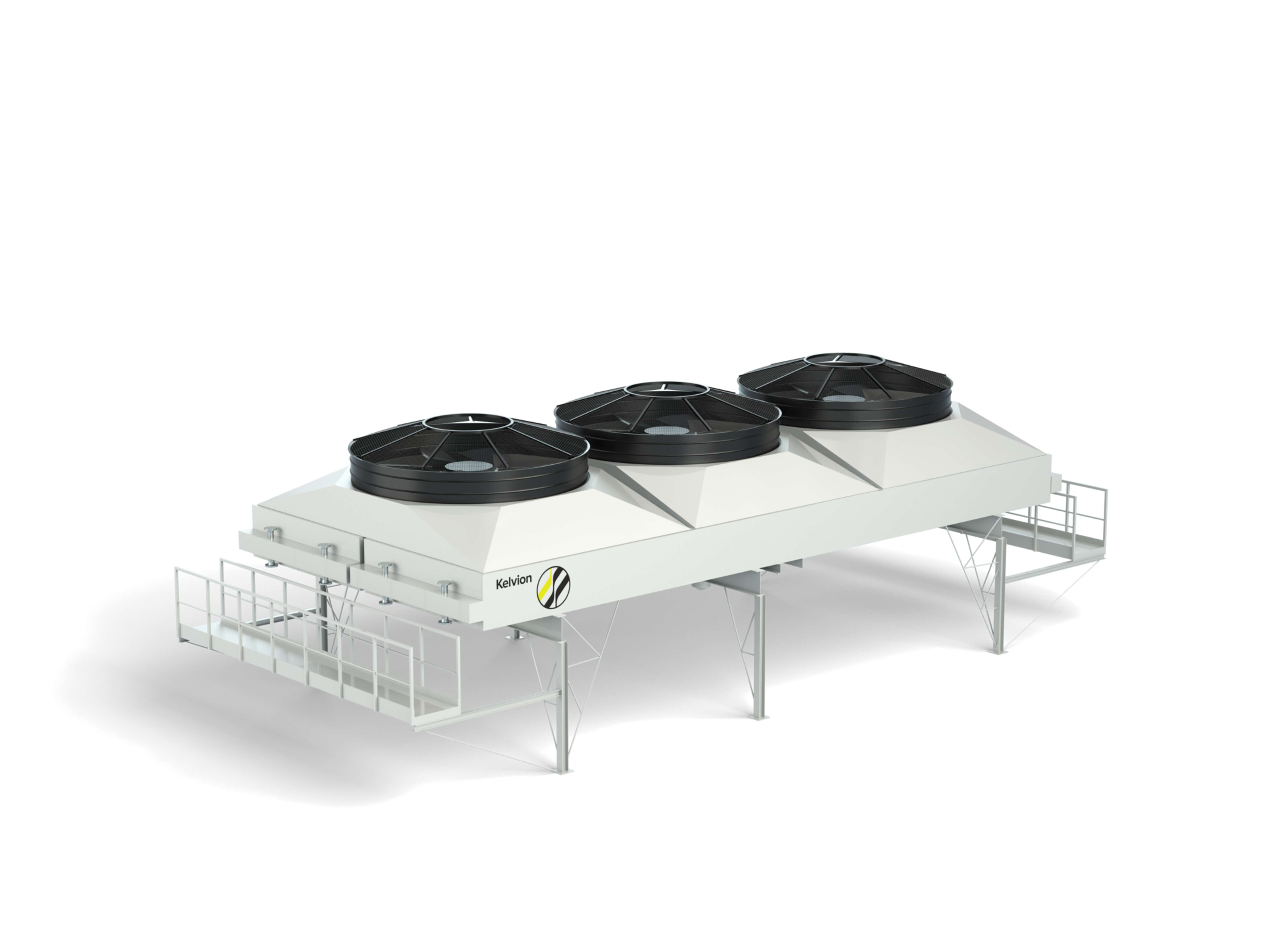
Combine dry efficiency with evaporative performance as needed; useful where one unit must cover base and peaks.
Applied in evaporative or condenser-side schemes; require water-quality management and drift/legionella controls.
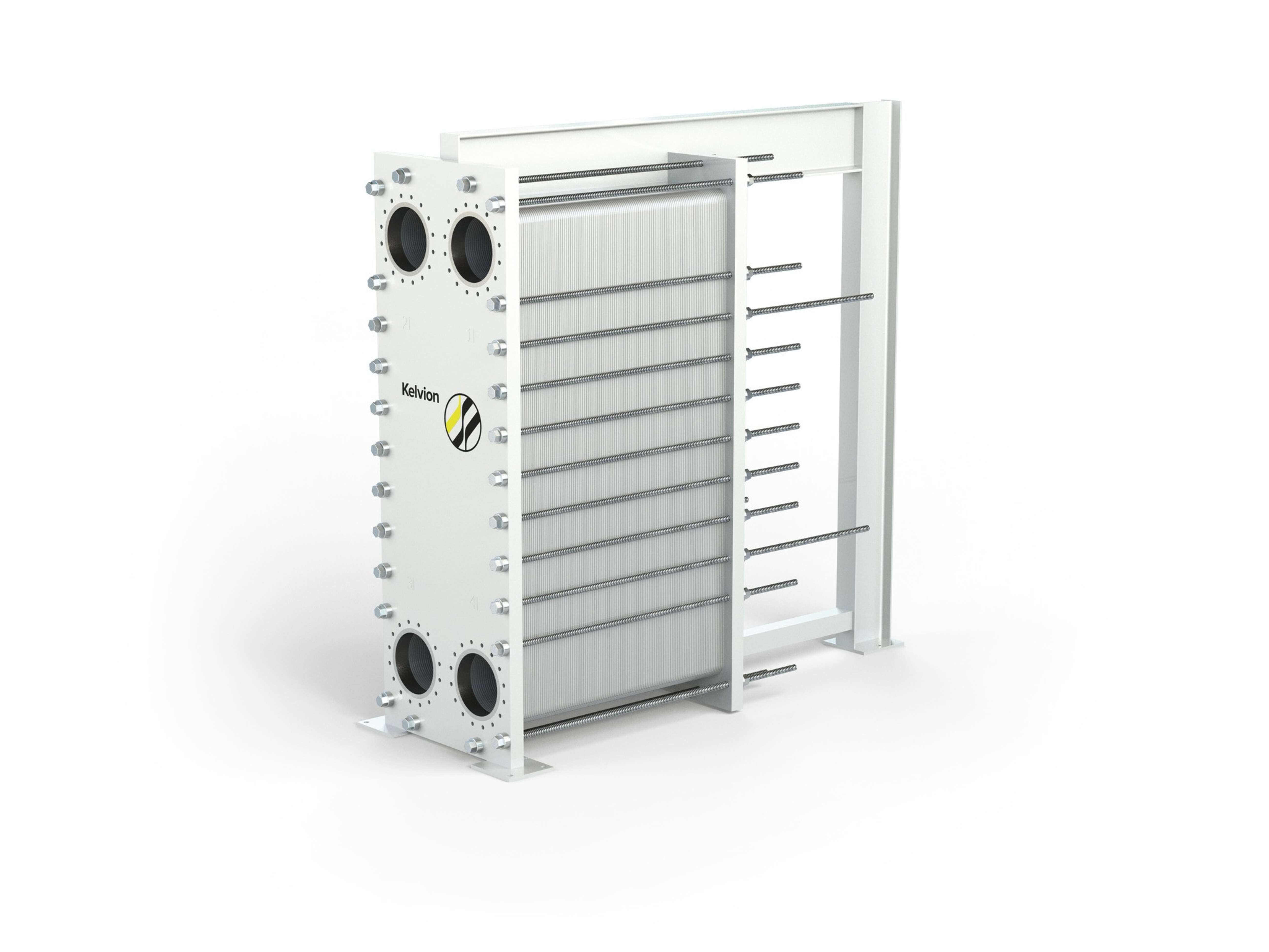
Provide hydraulic separation between data-centre circuits and the recovery side; material selection and plate patterning protect ΔT and pressure drop.
Lift temperature to network set-points; selection by required lift, part-load efficiency (SCOP) and controls so recovery follows IT load.
Buffer tanks, variable-speed fans/pumps and proper valving/flow-balance keep ΔT stable and align export with demand.
What increases the recovery potential?
Run “hotter” where permissible
- Raising return temperatures within equipment limits improves heat-pump COP and increases usable export.
Match rejection and recovery
- Dry/air-fin for low water use and predictable OPEX.
- Adiabatic/hybrid where peak-day approach is tight or network set-points are demanding.
- Cooling towers/ACC for specific evaporative or condenser-side schemes.
Hydraulics & control
- Maintain stable ΔT across exchangers with balanced flows and variable-speed fans/pumps; treat WHR as load-following so core cooling isn’t penalised.
Phasing & delivery
- Use pre-engineered modules or site-erected arrays to align capacity with staged IT growth and network offtake ramp-up.
Water & sustainability
- Prioritise water-saving options (dry/air-fin) where feasible; use adiabatic assist only for hot-day headroom.



FAQ – Waste Heat Recovery Solutions
Free cooling reduces electrical demand by using favourable ambient conditions (primarily via dry/air-fin operation), while heat recovery captures usable return heat for buildings or district networks; designed together, they lower OPEX without compromising export potential.
- Complementary roles: Free cooling handles base rejection for most hours; heat recovery taps the return side when temperatures and demand align (often with a heat-pump interface).
- Temperature management: Running “hot” (within equipment limits) improves free-cooling hours and heat-pump COP, increasing both efficiency and export viability.
- Water strategy: Keep systems dry by default; enable adiabatic assist only on hot days to protect approach (ΔT) while maintaining low water use.
- Controls & phasing: Variable-speed fans/pumps, balanced flows and buffer tanks let export follow IT load without eroding free-cooling performance.
- Planning tip: Size coil surface and plate/shell-and-tube exchangers to hold set-points at peak ambient, then evaluate network set-points to right-size the heat pump.
In most projects, export is enabled by a heat-pump interface that lifts the temperature to network set-points and a hydraulically separated connection to protect both systems.
Typical steps:
- Couple the data-centre loop to the export side via heat exchangers to isolate fluids and pressures.
- Use a heat pump to reach the required supply temperature (commonly in the ~60–90 °C range, network-dependent).
- Ad buffer tanks to smooth demand mismatches and reduce on/off cycling.
- Implement controls and metering (supply/return, ΔT, flows, availability) so export follows IT load without compromising core cooling.
The right option depends on climate, water policy, target approach temperature (ΔT), available space and the need to interface with heat recovery.
- Dry/air-fin coolers offer water-saving operation and predictable OPEX. When correctly sized to peak ambient, they provide stable approaches and are a strong base case for most locations.
- Adiabatic coolers run dry for most of the year and use short adiabatic assists on hot days to lower intake-air temperature and add capacity. They are useful where peak-day margins are tight but water use must remain low.
- Hybrid coolers combine dry efficiency with evaporative performance in one unit. They are appropriate where a single footprint must cover base and peak conditions without oversizing.
- Cooling towers / air-cooled condensers (ACC) suit evaporative or condenser-side schemes and certain legacy plants. They require water-quality management and drift/Legionella controls but can deliver high capacities in compact spaces.
All four approaches can be engineered alongside heat-pump stages and plate or shell-and-tube heat exchangers to support waste-heat export.
Tracking the right indicators helps optimise recovery without harming base efficiency.
- Exported heat (MWh) and availability: shows delivered energy and how reliably it is provided.
- Network supply/return & ΔT: confirms that export meets temperature targets and that the network receives usable ΔT.
- Heat-pump COP / seasonal performance (SCOP): measures temperature-lift efficiency and operating cost over time.
- Approach temperatures across exchangers: ensures plate or tube bundles are clean and sized correctly, protecting ΔT and pump/fan power.
- PUE and WUE interactions: verifies that heat recovery does not degrade electrical or water efficiency of the data centre.
Programme timelines and future phases are influenced as much by delivery model as by equipment choice.
- Pre-engineered, factory-tested modules shorten commissioning and reduce site risk; they are well suited to time-critical upgrades.
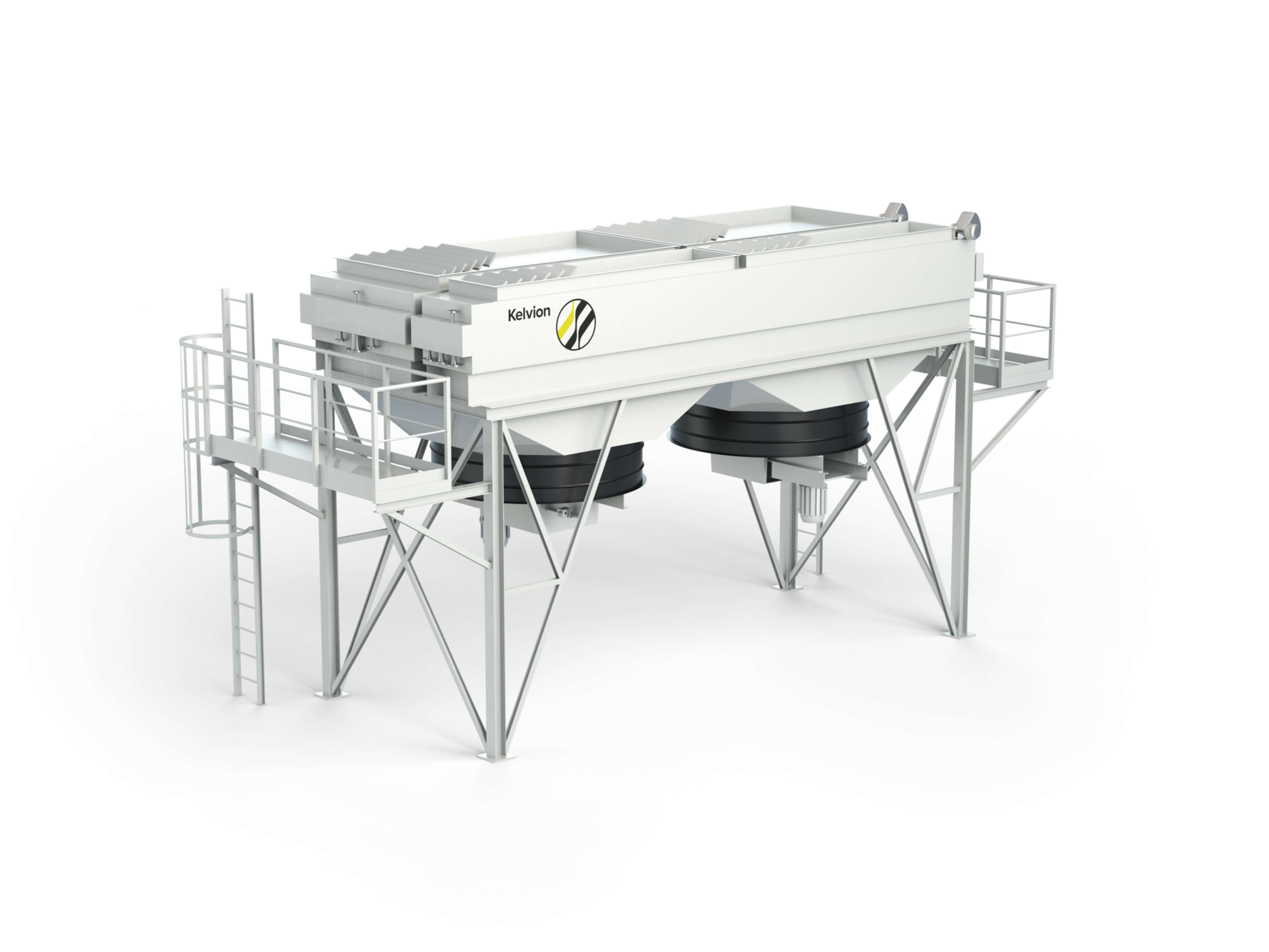
- Site-erected large air-fin fields provide very high capacities where transport limits apply and allow flexible layouts around plot constraints.
- Phased arrays align capacity with staged IT growth and with the ramp-up of network offtake.
- Early planning for logistics, cranage, electrical and water services, and access routes helps de-risk delivery and standardise future expansions.