How Are Air Fin Coolers Applied and Integrated in Refinery Operations?
Air Fin Coolers are a core element of refinery heat-management strategies, particularly where water availability or regulatory constraints limit wet cooling. Their ability to reject heat solely through ambient air makes them suitable for a wide range of process duties, from overhead vapour condensation to compressor discharge cooling. For refinery operators, the decision to deploy an Air Fin Cooler is closely linked to process stability, mechanical integrity and long-term asset reliability.
The Role of Air Fin Coolers in Modern Refineries
In a modern refinery, heat management is strongly linked to overall site economics. Every fractionation step, catalytic reaction or compression stage generates heat that must be removed in a controlled way. Air fin coolers support this by providing dry-type heat rejection using ambient air as the cooling medium. They are typically deployed wherever direct water cooling would be inefficient, risk-prone or incompatible with the site concept.
Typical applications include atmospheric and vacuum distillation overhead systems, naphtha and diesel hydrotreating, hydrocracking, catalytic reforming, FCC main fractionator overheads and various gas compression stages. In these units, the air fin cooler defines important boundary conditions, such as product condensation temperature, compressor discharge temperature or the thermal stress level on downstream equipment. A stable performance of the cooler translates directly into stable column operation, catalyst life and mechanical integrity of rotating machinery.
The use of air as a cooling medium decouples the refinery from local water availability and quality. This is particularly relevant for sites in arid regions or locations with strict discharge limits. Instead of investing in large water treatment and cooling circuits, operators can implement a modular air-cooled concept that is easier to replicate across different sites. For multi-site companies, this standardisation reduces engineering effort and supports harmonised maintenance and spare-part strategies.
Integration into Refinery Process Units
The integration of an air fin cooler into a refinery unit begins at process design level. The process engineer defines required duty, inlet and outlet conditions, allowable pressure drops and expected operating envelope, including start-up, shutdown and upset scenarios. Based on this framework, the cooler is sized and configured, and its position in the plot plan is determined in coordination with piping, civil and structural engineering.
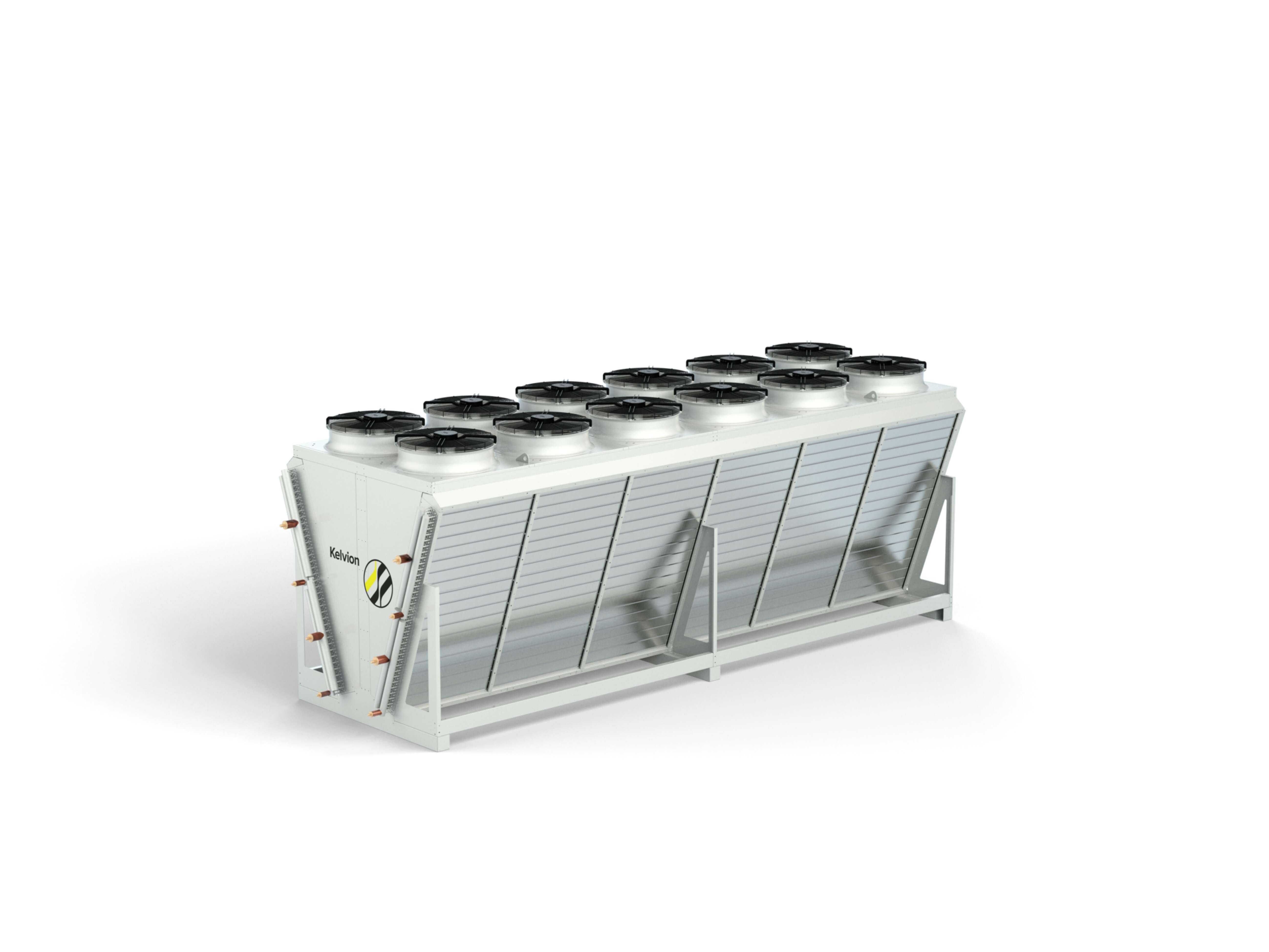
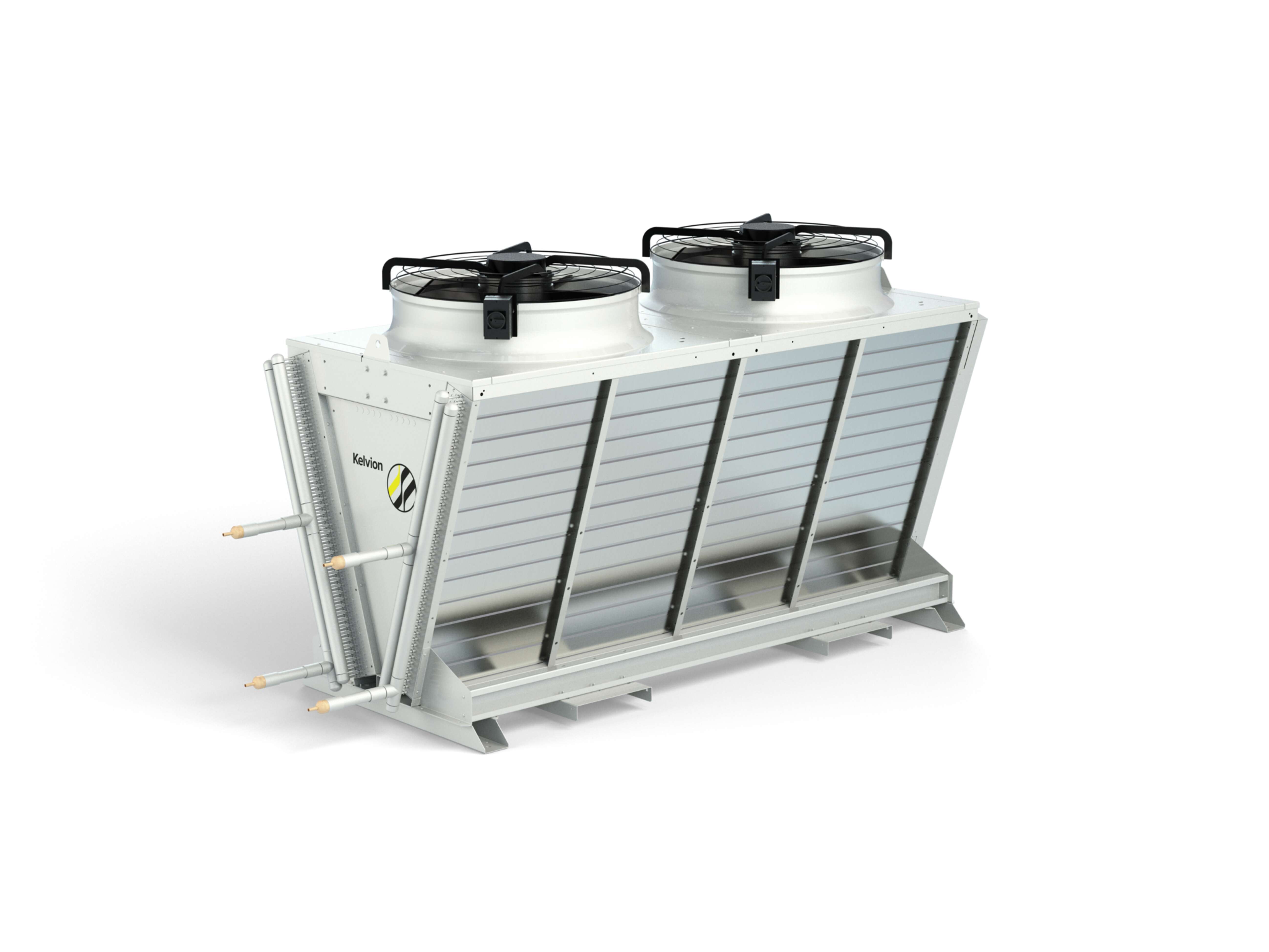
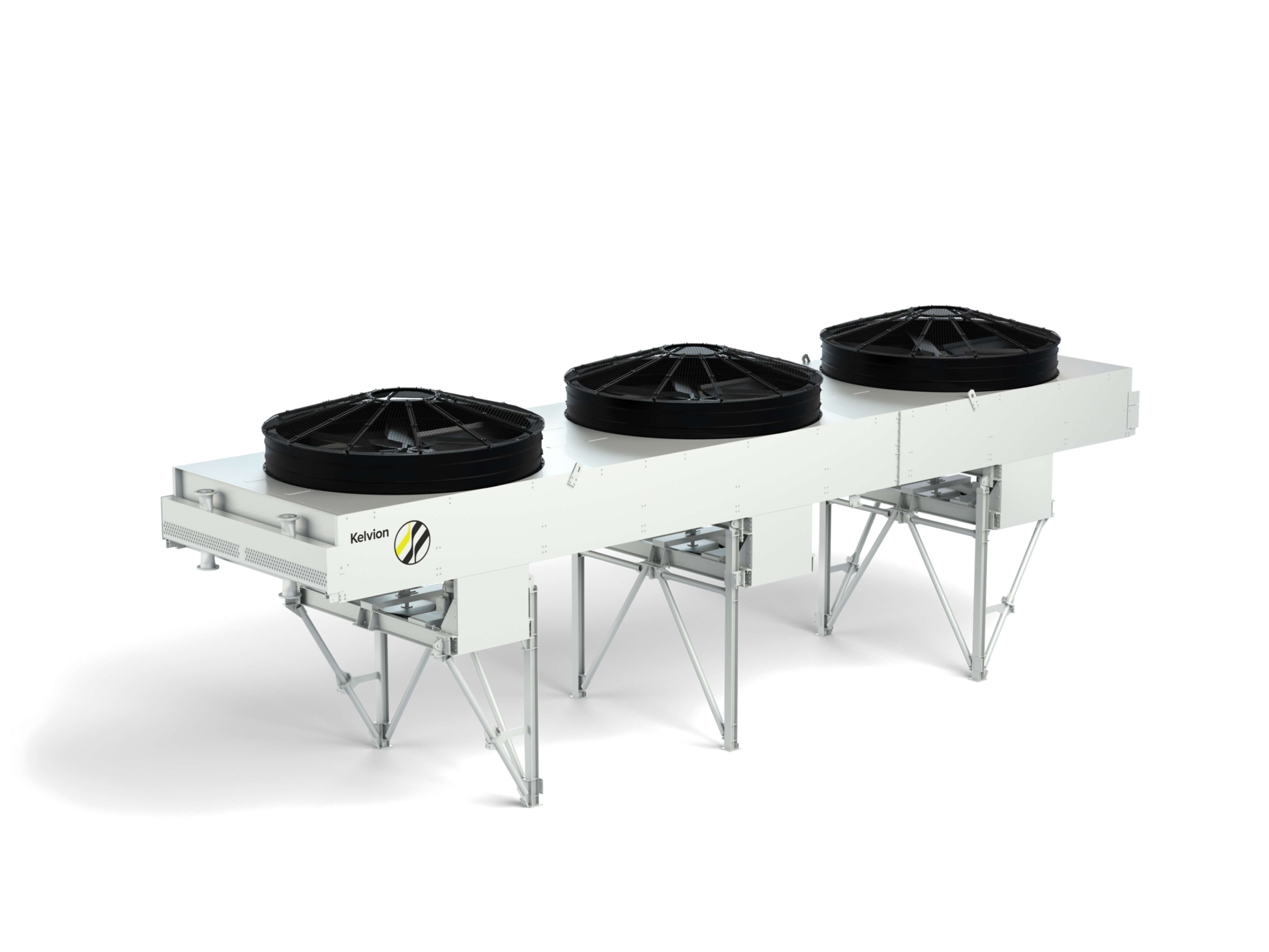
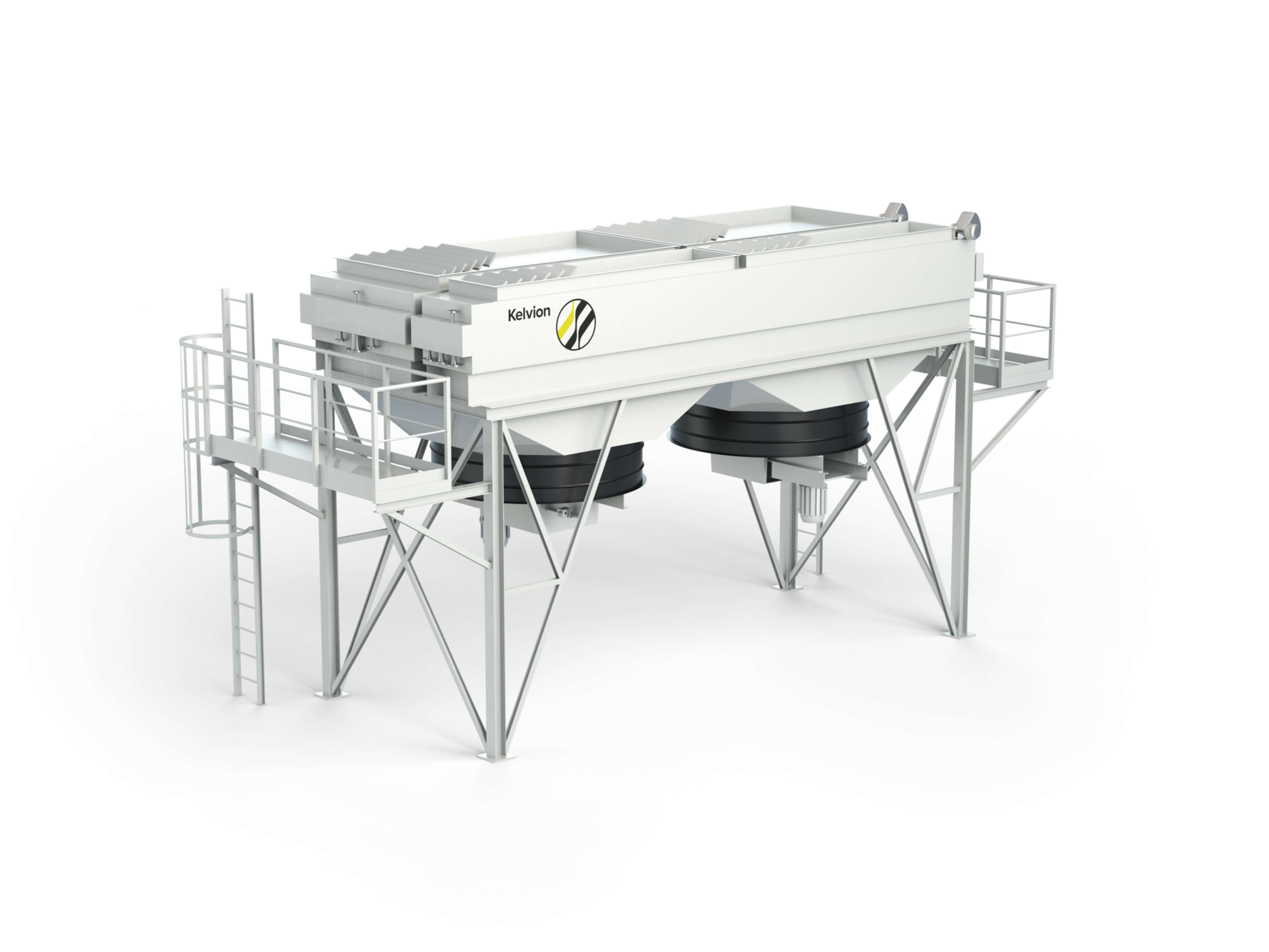
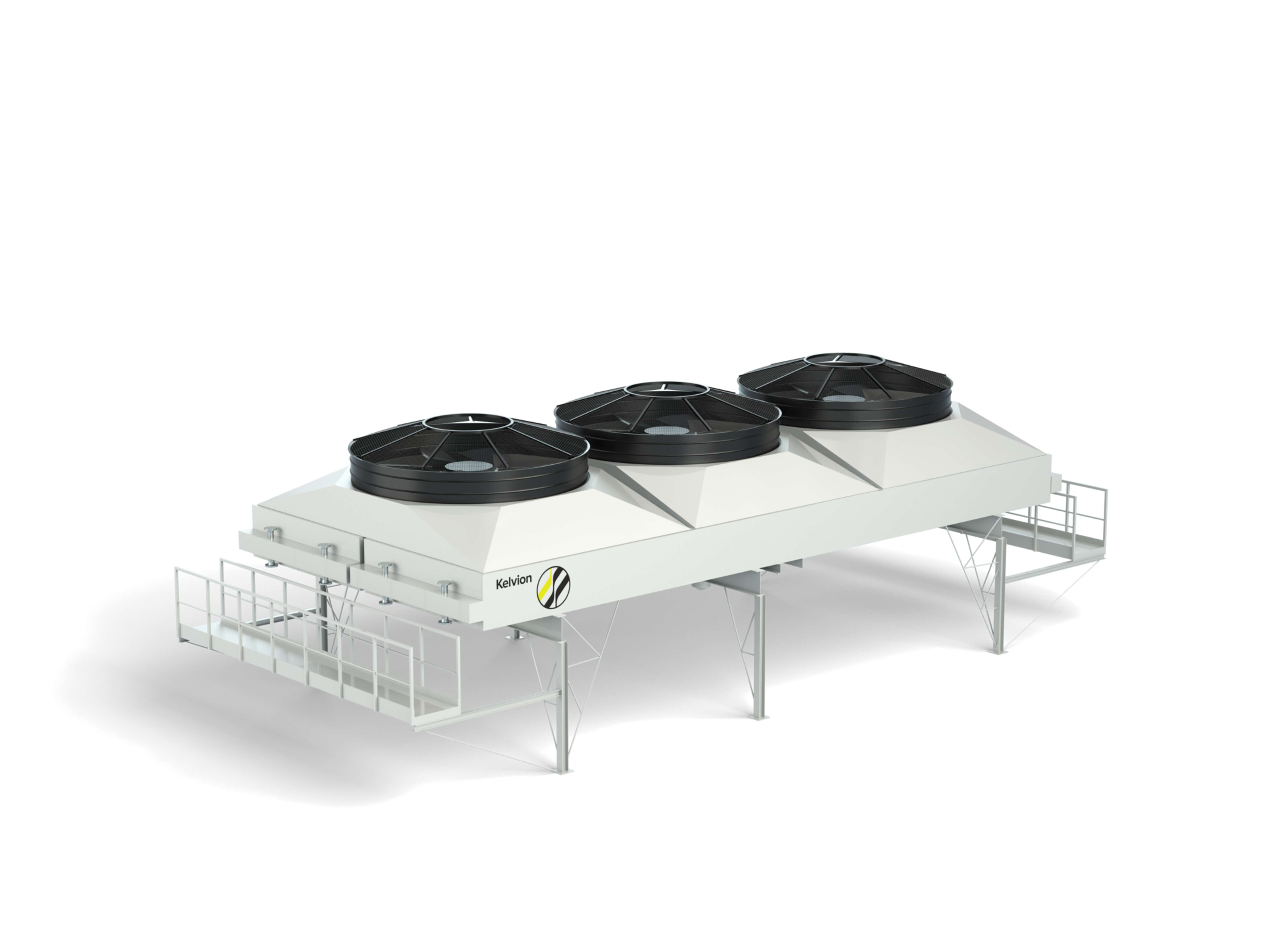
Air fin coolers are typically installed on elevated steel structures or pipe racks to ensure unobstructed airflow and safe access for inspection and maintenance. Their modular design – consisting of multiple bays, tube bundles and fan cells – provides redundancy and turn-down capability. Individual bays can be taken out of service for maintenance, while the remaining capacity continues to support essential unit operation within defined operating limits.
The piping arrangement is engineered to balance hydraulic behaviour and maintainability. This includes the distribution of two-phase flows in overhead condenser services, the avoidance of dead legs in product cooling duties, and sufficient flexibility to accommodate thermal expansion. Accessibility for bundle extraction, fan replacement or header inspection is addressed early in the layout phase. In refinery environments with limited space, this coordination between process, piping, structural and maintenance engineering often determines whether an air fin cooler solution is feasible at all.
Design Considerations for Refinery Conditions
Designing an air fin cooler for refinery service means accommodating a broad range of boundary conditions. These include high operating pressures, elevated fluid temperatures, frequent load changes and a significant spread between minimum and maximum ambient temperatures. The cooler must perform reliably at design ambient – often defined as a relatively high temperature – while still providing adequate cooling at lower ambient conditions without causing operational issues such as excessive condensation or subcooling.
Thermal design focuses on defining the required heat-transfer area, fin geometry and air-side mass flow. Fouling tendencies of the process fluid are taken into account via appropriate fouling factors. In refinery service, fouling behaviour can change over time with feedstock quality and process severity, so conservative assumptions are often necessary. Pressure drop limitations on the process side must be respected to avoid impacting column operation, pump NPSH margins or compressor energy consumption.
On the air side, design decisions include fan type, arrangement (forced draft or induced draft), blade profile and expected sound power levels. High air velocities improve heat transfer but also drive noise emissions and fan power demand. Refinery-specific noise limits – for example at plant boundaries or near control buildings – often require a detailed optimisation of fin spacing, fan speed and potential sound attenuation measures. The structural design must consider wind loads, seismic requirements and potential dynamic influences from adjacent equipment.
API 661 Compliance and Mechanical Integrity
For refinery applications, air fin coolers are typically specified in accordance with API 661. The standard defines minimum requirements for design, materials, fabrication, inspection and testing of air-cooled heat exchangers in petroleum, petrochemical and natural-gas industries. For operators, API 661 compliance provides a transparent framework for procurement, quality assurance and mechanical integrity management.
Mechanically, the cooler must withstand internal pressure cycles, external loads and combined stresses over a long service life. Tube-to-tubesheet joints, headers, nozzles, supports and structural members are analysed for static and cyclic loads. Finite Element Method (FEM) studies are often applied to critical regions, especially where local stress concentrations are expected or where thermal expansion between connected components cannot be neglected.
Vibration control is a major topic in refinery environments. Process-induced vibrations, flow-induced tube vibrations and the interaction between fan-induced excitation and structural natural frequencies are all assessed during design. Appropriate support spacing, tube bundle bracing, stiffer frame designs or tuned mass damping solutions may be required, depending on the application. The target is to prevent tube fatigue, header cracking or loosening of bolted joints, which could otherwise lead to leaks and unplanned shutdowns.
Environmental and Operational Benefits
From an environmental perspective, the main advantage of using an air fin cooler in refinery service is the complete avoidance of cooling water consumption for the associated duty. No intake structures, cooling towers, water treatment units or blowdown facilities are required. This directly reduces water usage, minimises chemical consumption and simplifies compliance with water-related regulations.
In many regions, water availability has become a strategic risk. By shifting significant cooling duties from water-based systems to air fin coolers, refineries can reduce their exposure to water scarcity, droughts or tightening discharge limits. This often improves the resilience of the site and aligns with corporate sustainability targets. The absence of visible plumes and water drift also reduces potential impact on neighbouring facilities, infrastructure and traffic routes.
Operationally, air fin coolers have a simple process concept, with relatively few components in contact with the process fluid. This translates into straightforward inspection routines and reduced risk of biological growth, scaling or corrosion that typically affect cooling water circuits. The reduction of interfaces between process and cooling water minimises cross-contamination risks and associated monitoring needs. For operators, this means fewer variables to control and a clearer focus on mechanical condition, vibration behaviour and air-side cleanliness.
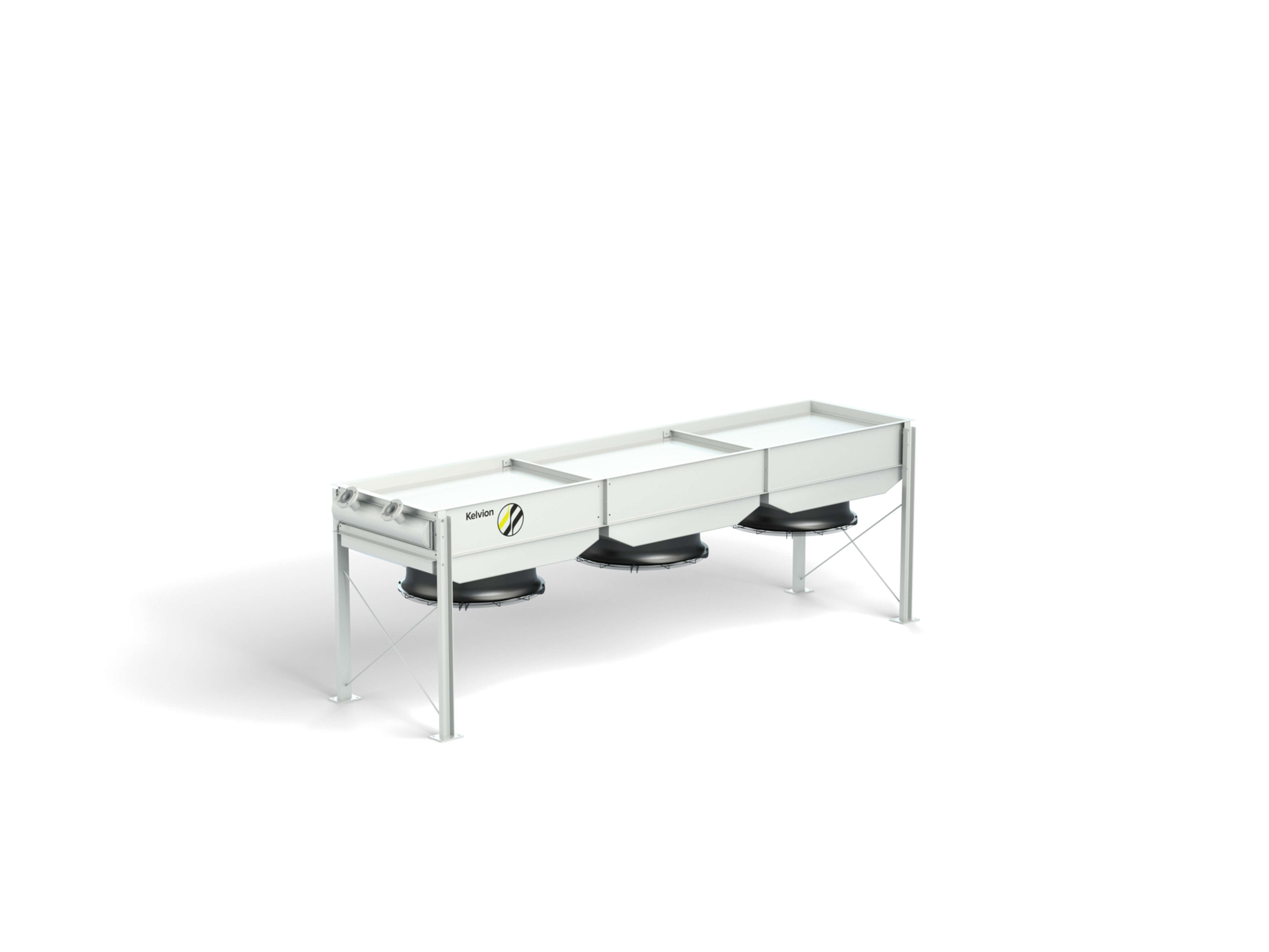
The electrical power consumed by fan drives represents the main operating cost element of an air fin cooler. For refinery operators, it is therefore essential to optimise the system’s efficiency across the full operating envelope rather than only at design point. Variable-frequency drives (VFDs) for fan motors have become a standard tool for this purpose. They enable precise adjustment of air flow to current process demand and ambient conditions, avoiding unnecessary energy consumption at part load or in cooler ambient weather.
Control strategies typically combine temperature measurements at process outlet, ambient sensors and, in some cases, fan motor feedback. The control system may operate in steps (on/off of fan cells), via continuous speed modulation, or by a combination of both. In more advanced setups, louvres or variable-pitch fans are integrated into the control philosophy to fine-tune airflow distribution. The goal is to maintain stable outlet temperatures, while minimising power draw and avoiding excessive cycling of fans and drives.
Digital tools extend this approach into lifecycle management. Computational Fluid Dynamics is used during design to reduce maldistribution in the air flow, identify potential recirculation zones and optimise fin and fan geometries. Later, digital twins link operational data with the original design model. Degradation effects, such as fin fouling or changes in process conditions, can be quantified by comparing actual performance with the expected behaviour from the design model. This supports evidence-based decisions on cleaning intervals, component upgrades or debottlenecking measures.
The long-term performance of an air fin cooler in refinery service is not determined solely at the design stage. Maintenance strategies and operational discipline play an equally important role. Over time, airborne dust, process-related aerosols and other contaminants deposit on fin surfaces and restrict airflow. Even modest fouling of the air side can lead to noticeable increases in approach temperature and fan power consumption. Regular inspection and cleaning regimes are therefore essential.
Mechanical maintenance focuses on fan systems, motors, gearboxes (where present), bearings and structural elements. Vibration monitoring helps detect imbalances or misalignment at an early stage. For tube bundles and headers, inspections concentrate on corrosion, erosion and potential mechanical damage. The design of the air fin cooler should facilitate all these activities by providing safe access platforms, lifting points, removable panels and bundle extraction routes that are compatible with site logistics.
Lifecycle management increasingly uses condition-based approaches rather than purely time-based intervals. Vibration trends, temperature deviations, motor-current patterns and process performance indicators are evaluated to derive maintenance priorities. In many refineries, air fin coolers are included in broader reliability programmes, together with rotating equipment and process-critical heat exchangers. Modular replacement concepts – for example, exchanging individual fans, motors or tube bundles during planned shutdowns – help maintain performance while keeping downtime and costs under control.
FAQ: Air Fin Coolers in Refinery Operations
Air fin coolers provide dry-type heat rejection using ambient air, which eliminates dependence on cooling water and the associated treatment, monitoring and discharge systems. In refinery service, this is particularly advantageous in regions with scarce water resources or strict environmental regulations. Their modular design and API 661-based engineering make them suitable for a wide range of refinery duties, from overhead condensation to compressor discharge cooling.
Air fin coolers are normally positioned on elevated steel structures or pipe racks, often above process units or adjacent to them. This ensures unobstructed air intake and discharge, reduces the risk of hot-air recirculation and enables safe access for inspection. Typical installations are associated with distillation units, hydrotreaters, hydrocrackers, reformers, FCC units and gas compression trains.
By replacing or supplementing water-based cooling systems, air fin coolers reduce water consumption, chemical usage and effluent volume. They also avoid visible plumes and water drift, which can be relevant in sensitive environments. In many environmental reports and sustainability strategies, the shift from water cooling to air fin coolers is considered a significant contribution to reduced environmental impact and improved site resilience.
Key risks include vibration-induced fatigue, inadequate consideration of thermal expansion, underestimation of fouling tendencies and insufficient attention to access for inspection and maintenance. If these aspects are not addressed during design, the result can be premature tube failures, leaks, reduced thermal performance or elevated fan power consumption. API 661 compliance, thorough mechanical analysis and a maintenance-oriented layout are effective measures to mitigate these risks.
Efficiency can be improved through optimised fin geometry, appropriate fan selection, well-designed airflow paths and the use of variable-speed drives. In operation, continuous performance monitoring and regular fin cleaning are crucial. Deviations between actual and expected approach temperatures provide an early indication of degradation. Based on this data, targeted interventions – from cleaning campaigns to fan upgrades – can be planned, which reduce energy consumption and stabilise process conditions.