LNG Value Chain Optimisation – FAQ
Optimising the LNG value chain is about cutting energy intensity, preventing freeze-out and keeping trains stable from feed conditioning through liquefaction, transport, and regas/end use. The FAQs below focus on the decisions that matter most to engineers and operators – scheme design, efficiency levers, where heat exchangers earn their keep, and how site constraints shape technology choices – with practical detail you can use in design, retrofit, and day-to-day operations.
What defines a robust LNG scheme from feed to end use?
An LNG scheme is shaped by feed composition and variability, target capacity and plot/ambient, and downstream specifications for transport, regas and end use. The practical aim is a stable “liquefier-ready” feed, predictable refrigeration duty, and clean hand-offs to carriers and vaporizers without trips or re-cooling cycles.
- Upstream: pretreatment removes CO₂/H₂S, water and mercury to prevent freeze-out and materials damage.
- Midstream: cycle selection (SMR/DMR/C3MR), compressor maps and approach temperatures (ΔT) govern energy intensity and turndown.
- Downstream: boil-off gas (BOG) handling on carriers and vaporizer choice at regas determine losses, utilities and emissions.
What are the practical levers to lower energy intensity across the chain?
Energy falls when you reduce refrigeration/compression work, hold tight ΔT in heat exchange, and recover heat/cold sensibly – all while remaining operable at design-day ambient.
- Refrigeration: match cycle to climate/plot; minimise recycle and pressure drop; keep compressors in efficient regions.
- Heat exchange: design for clean, maintainable surfaces and realistic ΔT targets that you can hold in summer, not only in spring.
- Integration & control: reuse precool/intercool heat where viable; trend ΔT as an early fouling signal and schedule cleaning before parasitics rise.
Where do heat exchangers add the most value – and how do they protect uptime?
Heat exchangers are the backbone of LNG temperature control and phase change across the full chain. The achieved approach temperature (ΔT) at each step drives power, stability, and run length.
Primary cooling and separation on produced gas; exchangers trim compressor work, condense liquids, and stabilise feed to treatment.
Dehydration/acid-gas removal with knock-out/condensation duties; suitable plate/tube patterns protect ΔT and pressure drop before cryogenic service.
Main cryogenic exchanger plus pre-/intercoolers set refrigeration efficiency; stable ΔT and fouling resistance prevent icing and trips.
Inter/aftercoolers for boil-off-gas compression/reliquefaction reduce compressor work and safeguard downstream equipment.
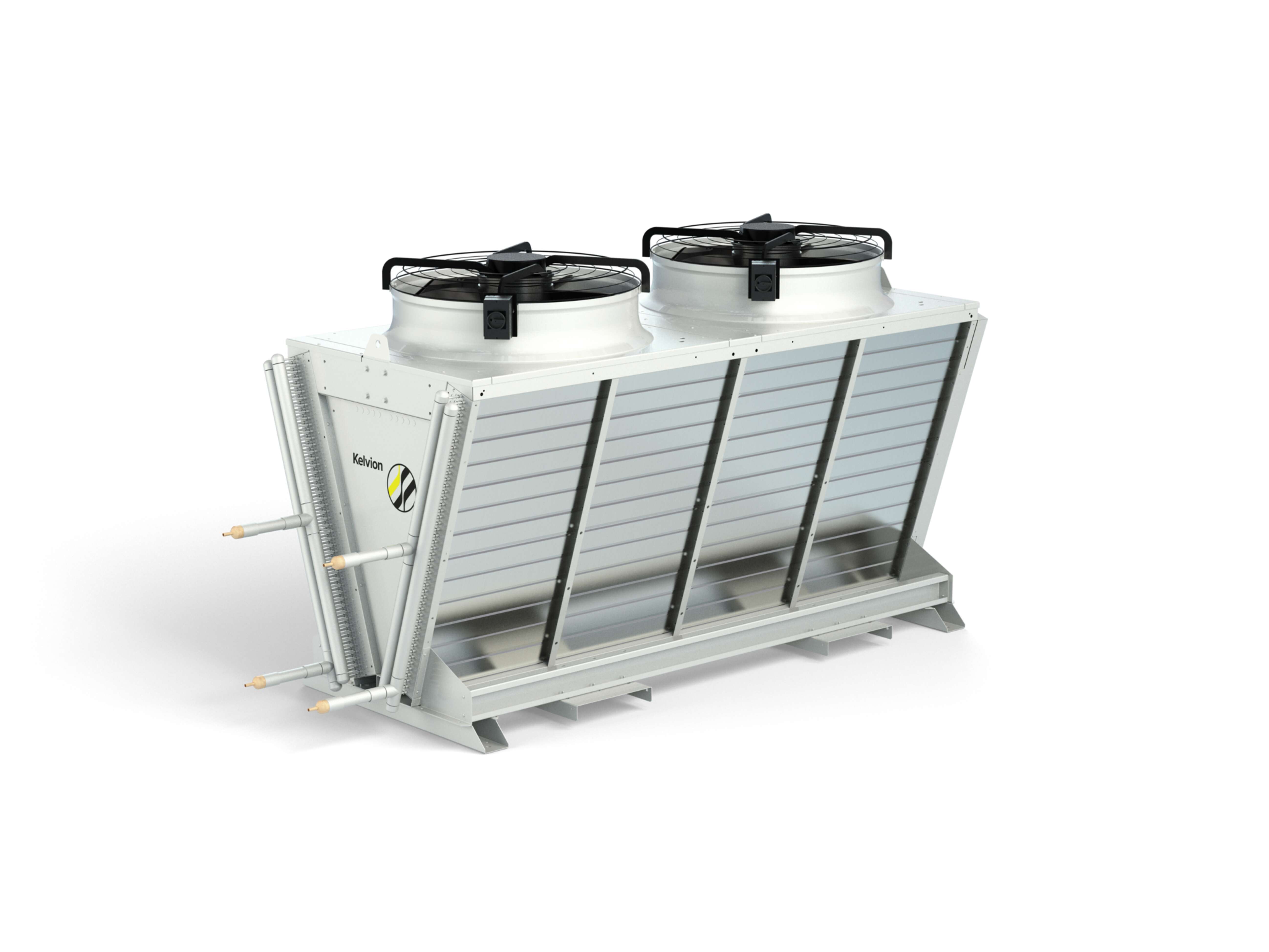
Plate/tube bundles and vaporizers (ORV/SCV/ambient) warm LNG reliably; coatings and biofouling control preserve performance.
Cold recovery for industrial users (e.g., air separation, cold chains) improves site efficiency when temperatures and offtake align.
How do you design heat exchangers for LNG duty?
Design starts with a precise duty definition and ends with a maintainable, code-compliant unit that holds a tight ΔT at design-day ambient without icing or excessive pressure drop.
- Define the duty precisely: Fluids/phases, flow ranges, inlet/outlet temperatures, allowable Δp, fouling factors, turndown, start-up/shutdown transients; include two-phase and BOG cases.
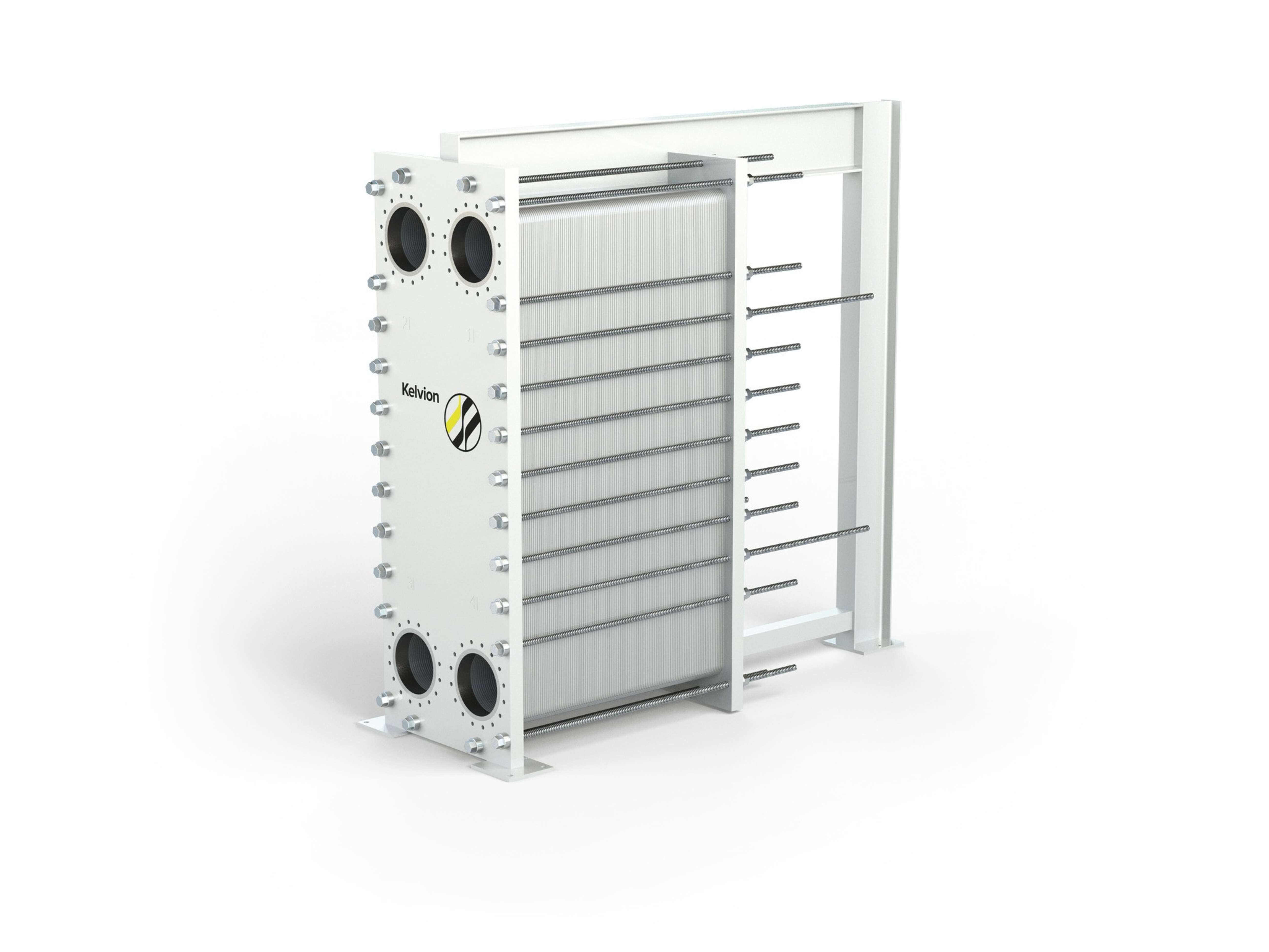
- Select families by constraints: Aluminium brazed/plate-fin (or coil-wound) for large cryogenic cold-box duties; shell-and-tube or plate-and-shell for higher pressure or fouling services; gasketed plate where serviceability and tight approaches are required.
- Thermal targets: Set realistic approach temperatures you can hold in summer; verify pinch locations, refrigerant windows, and seasonal heat-curve matching (SMR/DMR/C3MR).
- Hydraulics & control: Velocity for heat transfer without erosion/vibration; stable valves/VFDs to maintain ΔT at turndown; bypass/recirculation for start-up and de-icing.
- Materials & compatibility: Aluminium for cryogenic cores; 316L/duplex/titanium for plate/tube services as chloride/sulphide/mercury risks dictate; gaskets/elastomers (EPDM, NBR, FKM) matched to chemistry, temperature and oxygen exposure.
- Maintainability: Plan CIP or mechanical cleaning access, safe isolation, lifting/clearance; instrument ΔT and Δp across passes to detect fouling early.
- Mechanical integrity: Thermal cycling, differential expansion, fatigue, AIV/FIV; nozzle loads/support; coatings/corrosion protection.
- Compliance & documentation: ASME/EN/PED, datasheets, ITP/NDE, and guarantees tied to the operating envelope.

How do site conditions and policies guide technology choices?
Local ambient (dry/wet-bulb), water policy, emissions limits, utilities pricing, plot and logistics steer both process and equipment selection.
- Liquefaction: climate and footprint influence SMR/DMR/C3MR choices and exchanger sizing; utility prices tilt integration decisions.
- Transport: voyage profiles, insulation class and BOG strategy set energy use and emissions.
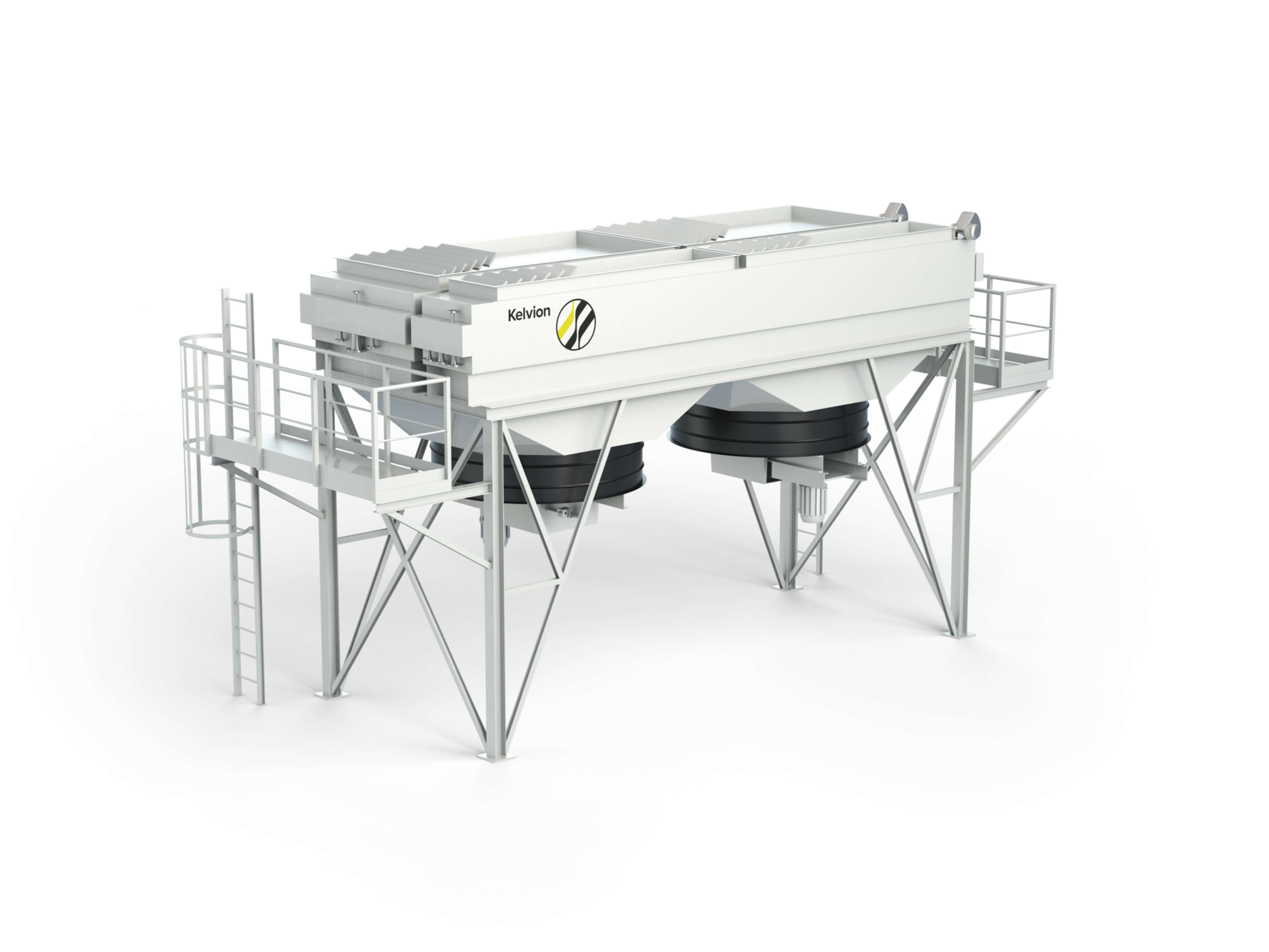
- Regasification: cold climates or tight water policies favour ambient/air or hybrid vaporizers; warm coastal sites often leverage seawater with robust fouling control.

FAQ – Improving Efficiency and Reliability Across the Chain
Energy intensity falls when refrigeration/compression power is optimised, heat-exchange approaches (ΔT) stay tight at summer design and useful cold/heat is recovered where economical. The most effective actions are to specify cleanable exchanger surfaces, choose compatible metallurgy that resists fouling and corrosion, and implement stable controls that hold set-points without oscillation at turndown. Where feasible, recover low-grade heat or cold into neighbouring users to trim utilities.
Upstream removal of CO₂, H₂S, water and mercury prevents freeze-out, corrosion and catalyst poisoning, reducing trips, flaring and re-cooling cycles. Consistent feed specifications also simplify refrigerant balance, lower compressor surge risk, and stabilise column and exchanger duties, extending run length between turnarounds.
Where capacity allows, reliquefaction minimises losses and controls storage pressure. If electrical headroom is limited, routing BOG to propulsion/power works well, provided compression is paired with proper inter- and aftercooling to protect equipment and efficiency. Instrument the sources of BOG – thermal ingress, handling operations, pressure control – so fixes target the real drivers.
Cold climates often favour ambient-air or hybrid vaporisers, as the environment supplies part of the duty. Sites with strict water policies typically avoid seawater-intensive options and select designs that operate dry most of the year, using short assists only in extremes. Choose by ambient profile, water availability, emissions targets, utility integration, and required turndown.
Focus on kWh per tonne LNG, compressor power and operating envelope, exchanger ΔT and cleanliness indicators and availability with cause-coded trips. Track emissions (CO₂ and methane slip) alongside energy to avoid counter-productive trade-offs. Review trends with maintenance planning so emerging issues are fixed before they shorten run length.
Design for modularity and phased capacity additions; reserve hydraulic, electrical and plot allowances for future equipment. Select exchangers and compressors with proven turndown to ride out demand variability. Where LNG serves multiple sinks – power, city-gas, bunkering, peak-shaving – align product quality and pressure with requirements early to prevent downstream constraints.